The DELL Poweredge R640 does support NVME with a bit of extra cabling. More specifically, the 10 bay chassis. In this tutorial I’ll show you exactly what cables you need to setup 2, 4, 8, or a complete 10 bay NVME system.
The first thing to know is there are 3 DELL cables used to make this happen. The first cable we’ll discuss supplies the first 2 ports with NVME:
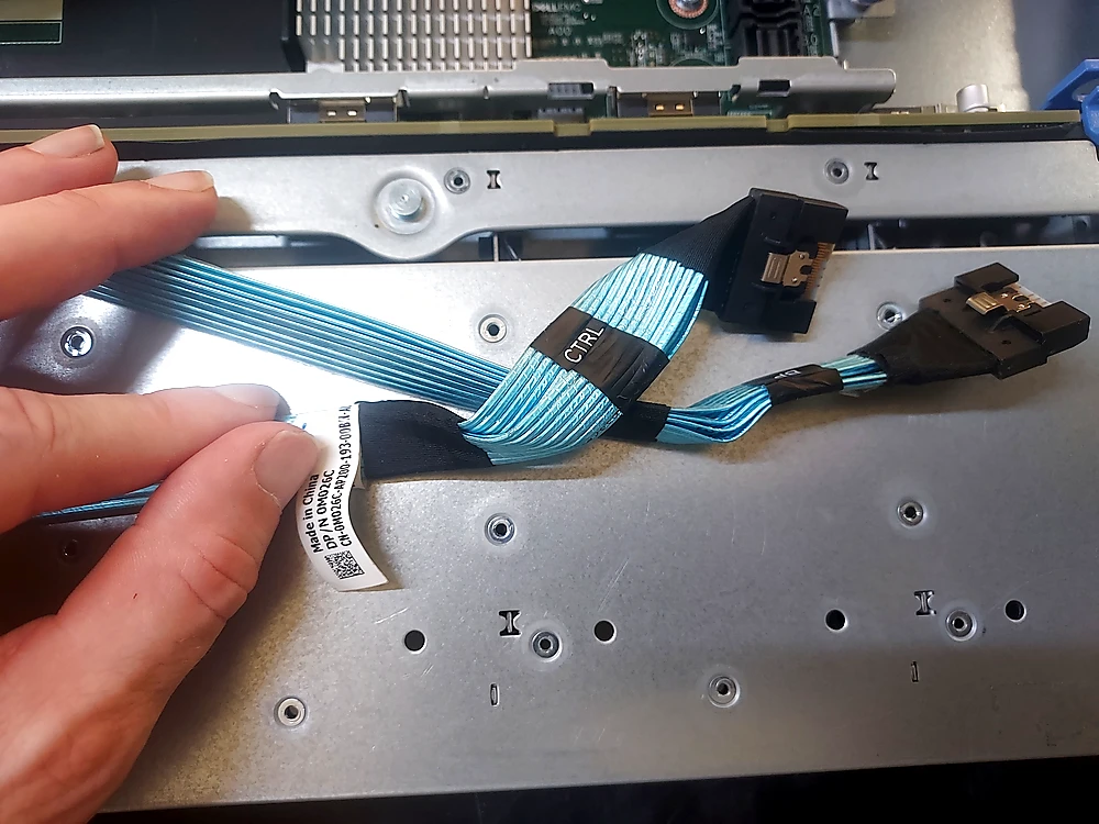
It’s essentially a slim SAS cable that connects to an NVME controller/expander card. The other cables we’ll discuss plug straight into the motherboard, but this one requires a separate card.
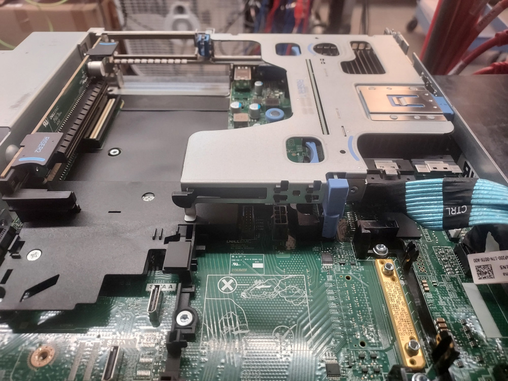
If you’re facing the server from the front, the connector is on the bottom left of the backplane. One end of the cable is labeled BP which is short for backplane. You’ll plug the BP side into the backplane.
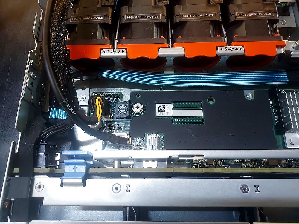
There will be some other cables in your way. You don’t have to unplug them but it does help. The other end of the cable is labeled CTRL. The cable will route alongside the backplane and then up the entire length of the right side of the chassis.
Now that the cable is routed appropriately it’s time to install the NVME controller card.
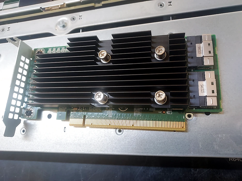
Install the card into riser 1 and then attach the cable to the first port.
Now you’ve officially supplied the first 2 drive bays with NVME. The remaining 8 bays also require their own cabling setup. If all you needed was support for 2 NVME drives you can stop here. No further work is required, just plug in your drives and fire up the server.
Let’s install the other 2 sets of cables. Each of these cables supplies 4 bays with NVME support. The set of cables labeled A0 and B0 supply bays 6 – 9. The set of cables labeled A1 and B1 supply bays 2 – 5. The previous cable we just installed supplies bays 0 – 1.
Don’t feel bad if you struggle installing these, they’re an absolute pain unless you’ve cabled hundreds of them and have experience.
Here’s what the next cable looks like:
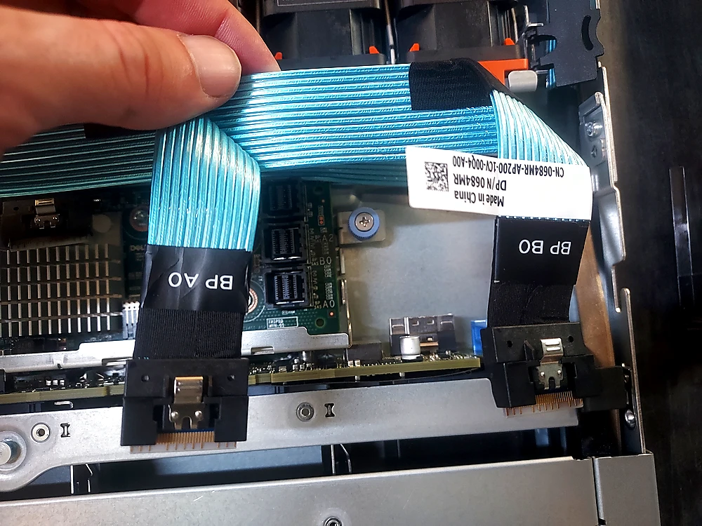
We will now move all the way to the right side of the backplane to the other Slim SAS connectors.
The cable labeled A0 and B0 will plug into their corresponding ports on the backplane (also labeled A0 and B0.)
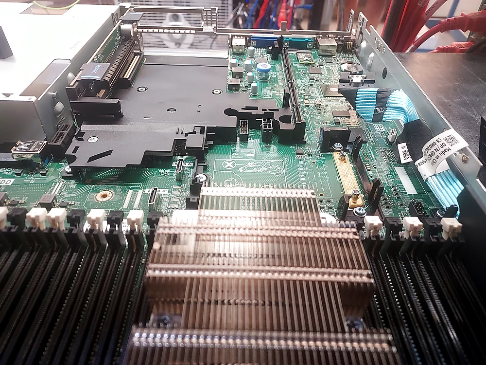
These cables will route all the way to the left side of the chassis, up the cable channel, and then plug in to the Slim SAS connectors in the left rear of the motherboard.
Now onto the other set of cables (A1 and B1)
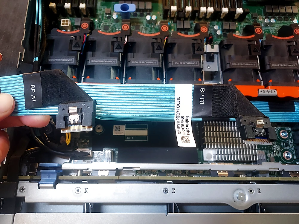
Do your best to tuck them under as best you can. Alongside the fans you’ll see hooks which keep the cables restrained and from popping out.
When it comes to routing them along the left side channel, I recommend pulling out the cables already installed. You don’t have to unplug them but it’s easier to route the NVME cables without them in the way. It’s much easier to tuck them in next to the NVME cables later.
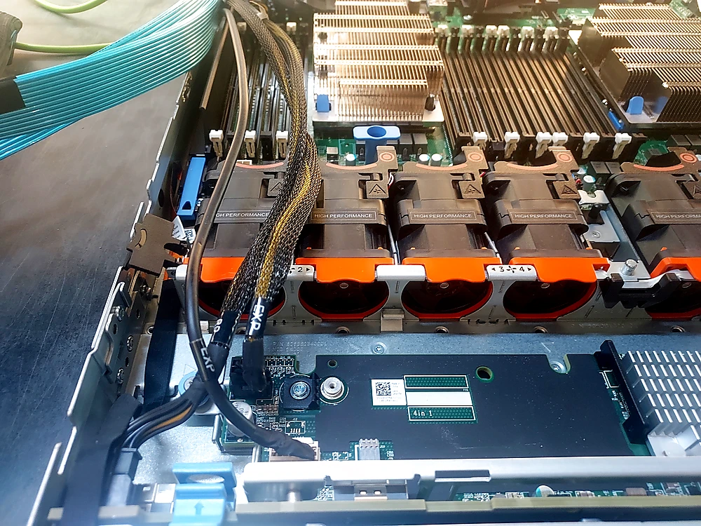
Once you have them tucked in nicely you’ll see where they have to plug in to in the rear.
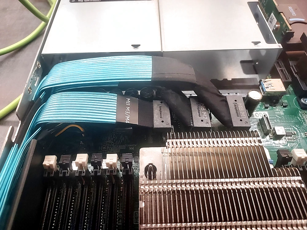
Find the ports labeled M1/M2/M3/M4 and just match them up.
And that’s all there is to it. If you’ve installed all 3 sets of cables you now have a server that supports 10 NVME drives. Keep in mind you don’t have to install all 3 sets. Once again, maybe you just want 4 bays with NVME connectivity. In that case, just install one set of the cables.
Thank you for reading.
Leave a Reply