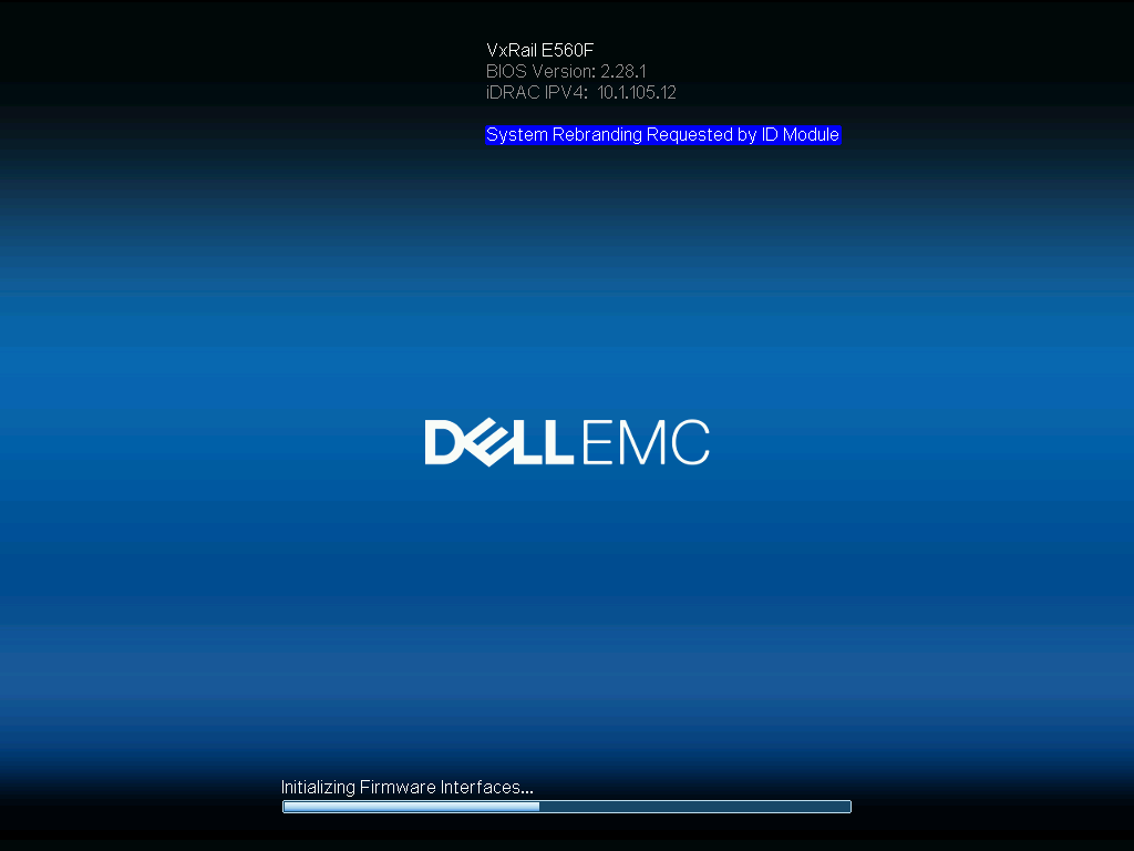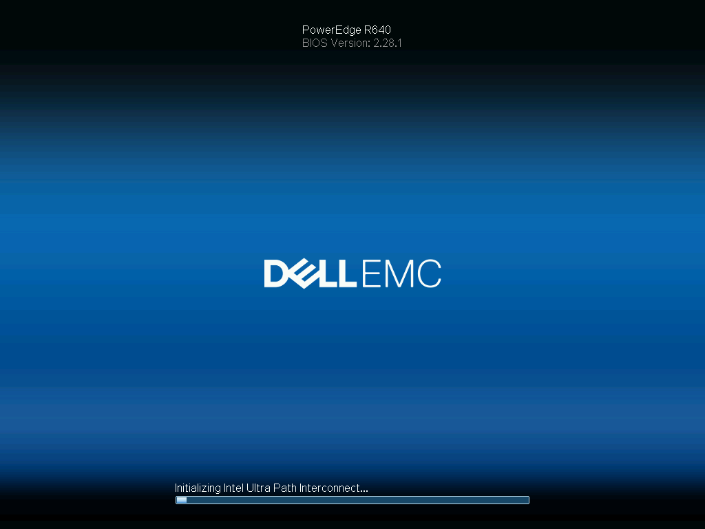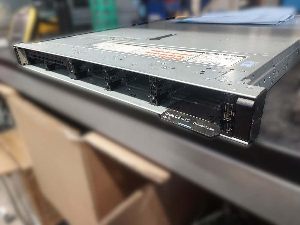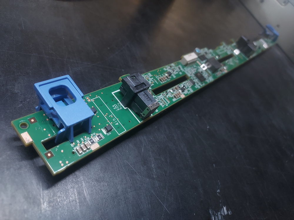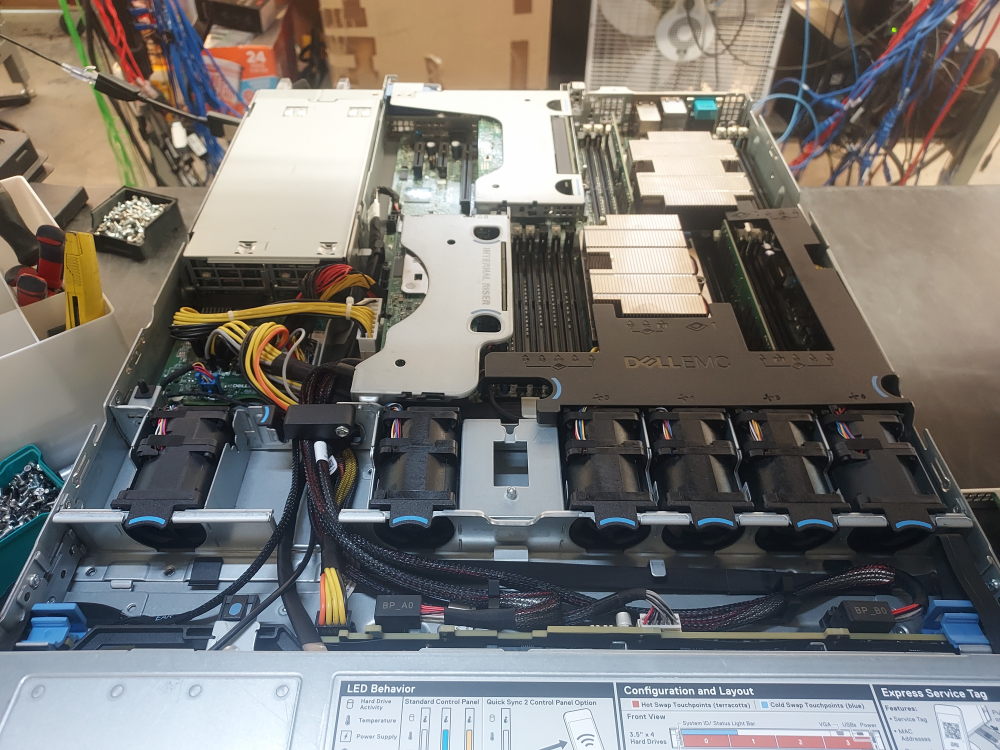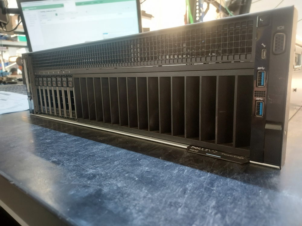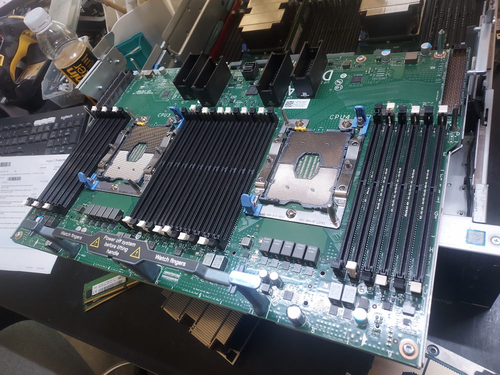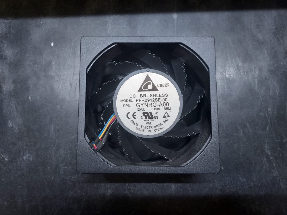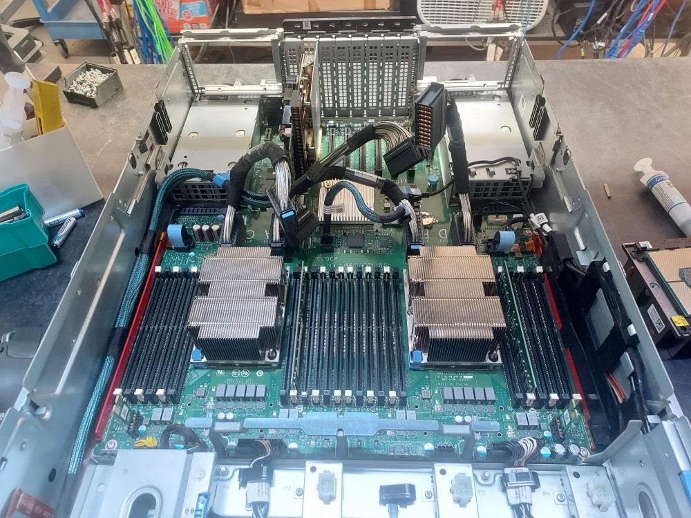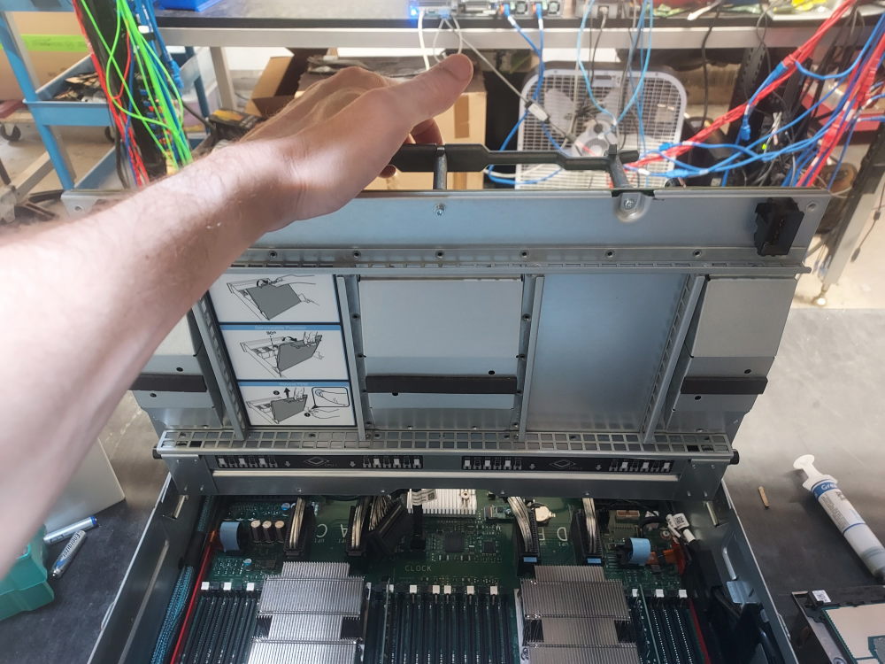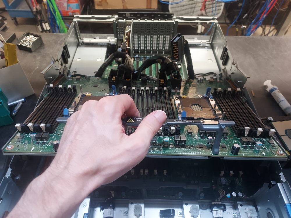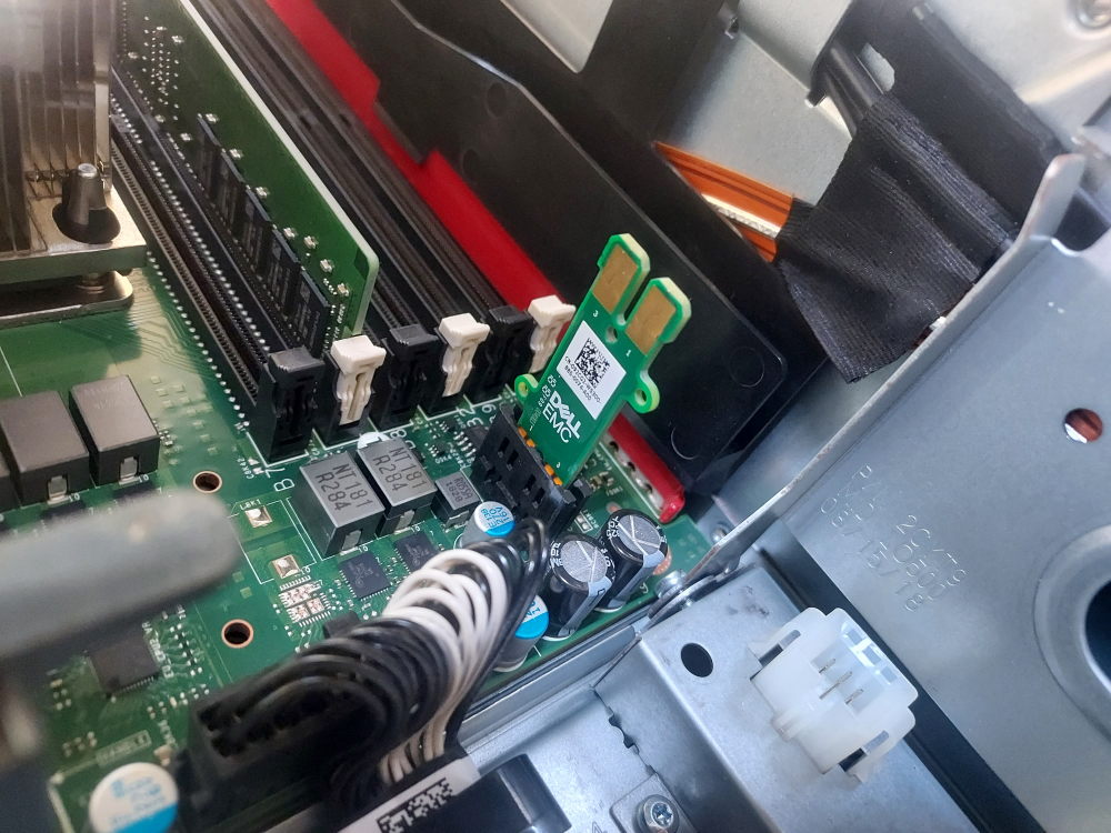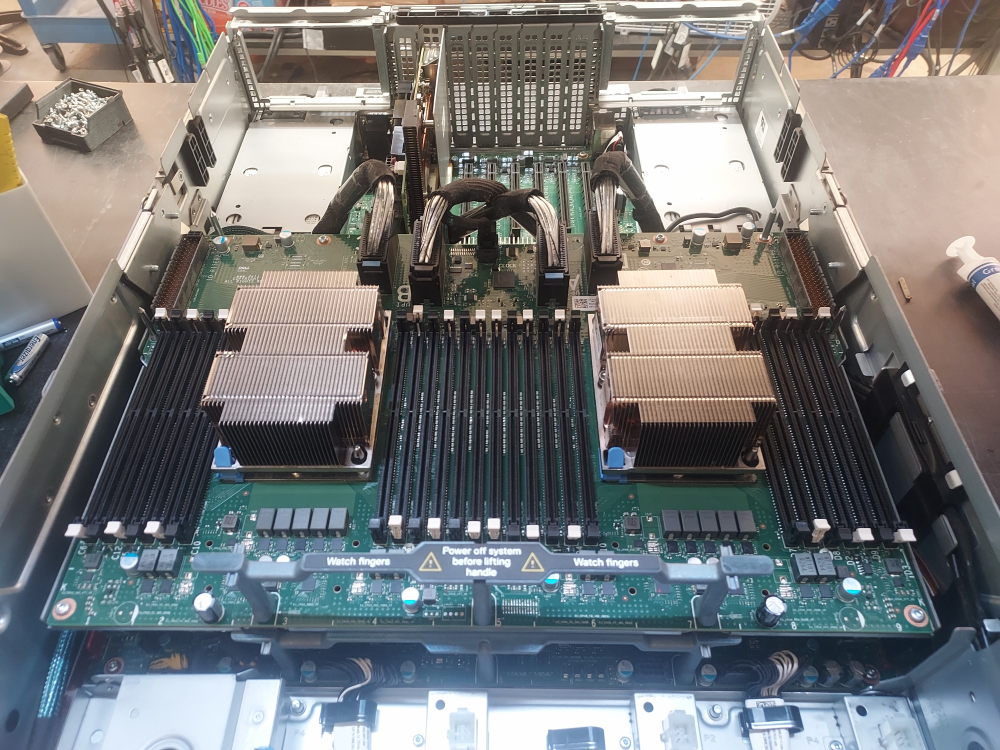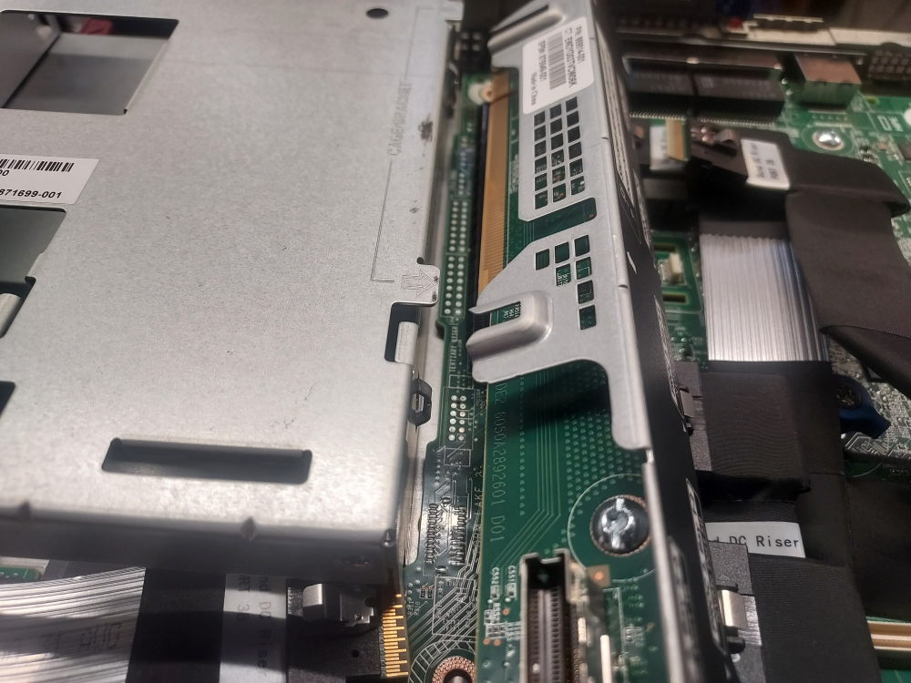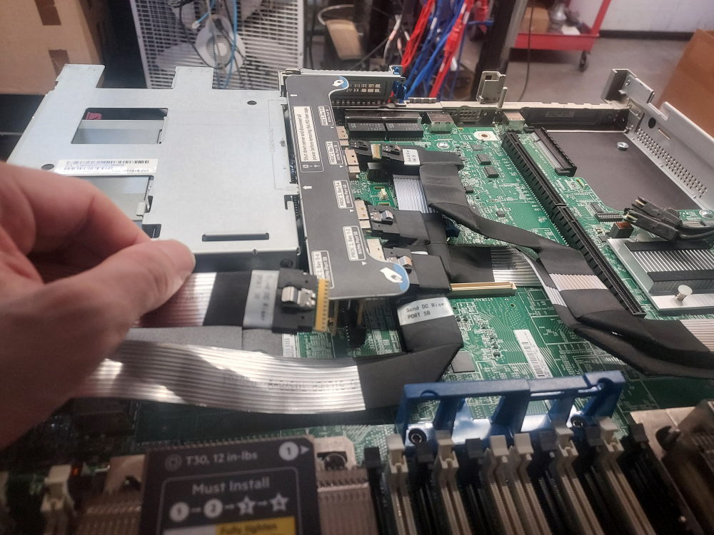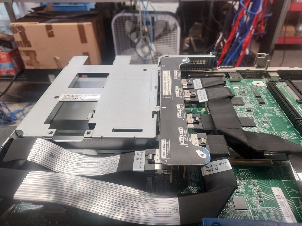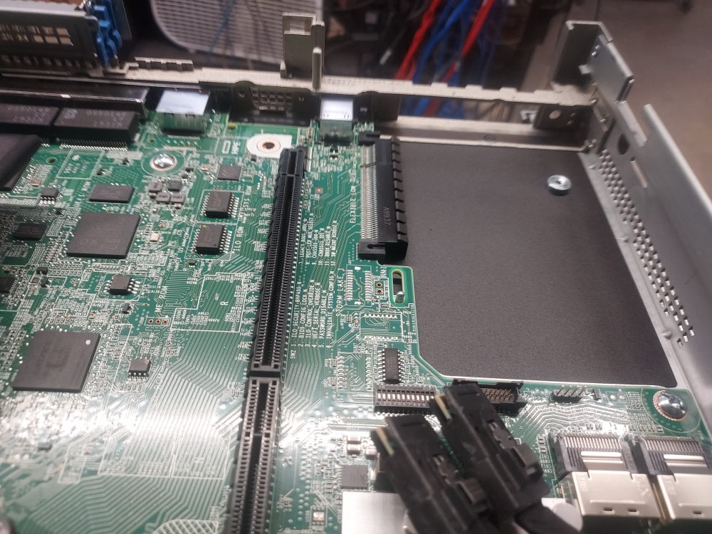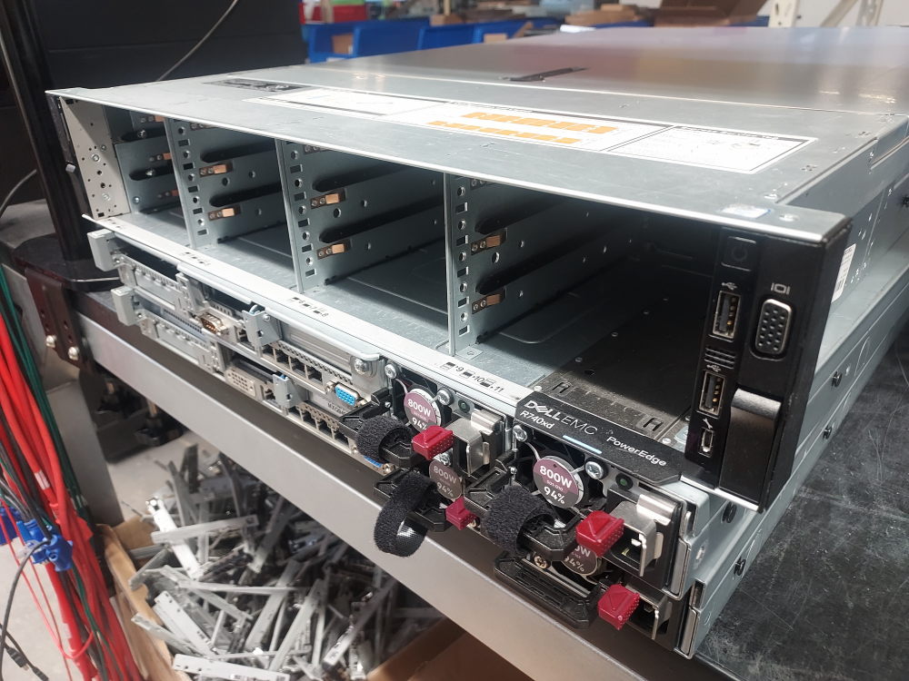
In this post I’ll be diving deep into building and configuring the Dell PowerEdge R740xd server. This will naturally build upon the R740 guide and include configuring hardware like flex bays and mid bays. The R740xd is essentially the R740 with more storage capabilities. This means a lot more storage bays in the front as well as support for storage in the rear and inside the chassis itself.
There are 2 chassis variations for the R740xd. One variation supports 12 large form factor drives through the front. The other supports 24 SFF drives. Both of these variations feature completely different backplanes. This is worth noting because it completely changes the type of cable you’ll need to install the supported flex bay or mid bay.
All of this will be covered in the guide.
Let’s start with the absolute bare minimum hardware requirements. As you verify the presence of the core hardware we’ll move on to specific configurations.
Essential Components
Before installing individual components it is important to identify the hardware required to turn the chassis into a functioning server. This section covers the major components that should be installed and verified before moving on to the rest of the build.
The goal is to start with a bare chassis and ensure that you have everything necessary to power on the system, recognize the installed hardware, access the storage devices, and eventually install an operating system.
Because the R740xd was available in several different storage and expansion configurations, the exact components required will depend on the chassis configuration you are building. In particular, the motherboard, storage backplane, cables, risers, storage controller, processors, memory, cooling system, and power supplies must be matched to the specific R740xd configuration.
Motherboard
The motherboard should already be installed in the chassis and securely fastened in place. It serves as the central connection point for nearly all of the server’s hardware.
The processors and memory modules are installed directly onto the motherboard, while the power supplies connect to the system through the rear of the chassis. PCIe risers attach to the motherboard to provide expansion slots, and the storage backplane connects to the system board and, depending on the configuration, to a PERC RAID controller or HBA. The hot-swap fan modules also connect to the motherboard.
Before installing additional components, make sure the motherboard is properly seated and secured inside the chassis. A loose, incorrectly installed, or damaged system board can prevent the server from powering on or cause individual hardware components to malfunction.
Storage Backplane and Cables
The storage backplane is one of the most important components of the R740xd because the server was designed around multiple high-density storage configurations. Depending on the chassis, the R740xd can use different combinations of 2.5-inch or 3.5-inch drive bays, as well as configurations that support additional internal or rear-mounted storage.
The backplane provides the electrical and data connections between the installed drives and the rest of the server. It also supplies power to the drive bays and contains the connectors required to interface with the system board and storage controller.
The exact backplane and cabling required will depend on the R740xd configuration.
Click here for 12 bay configuration
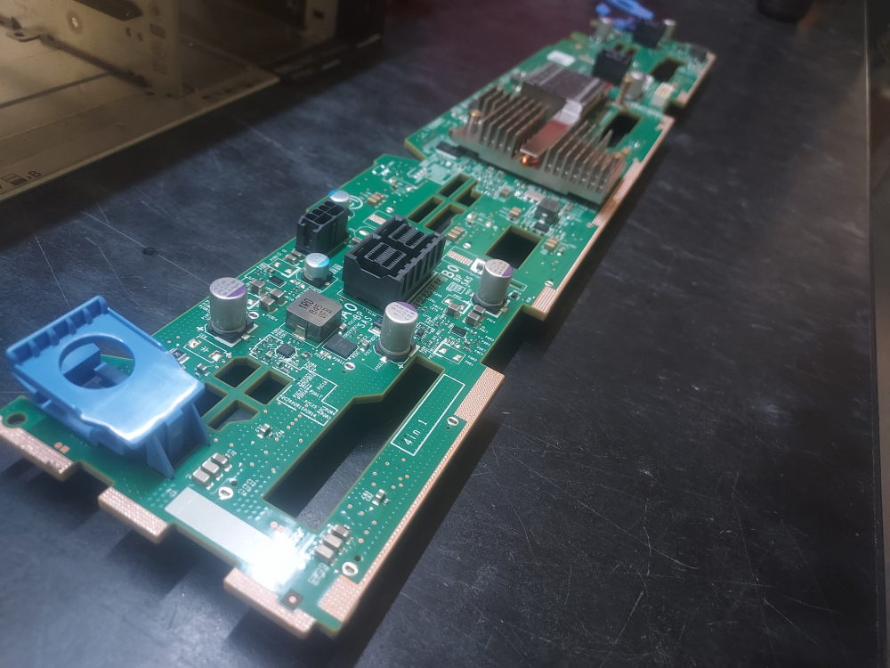
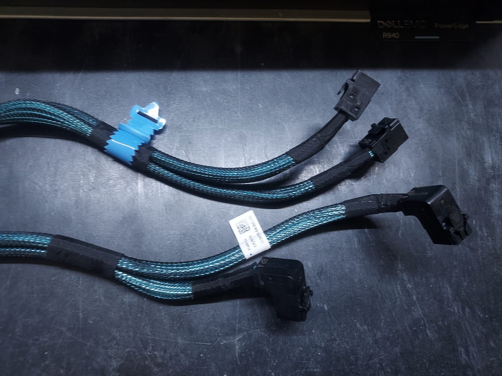
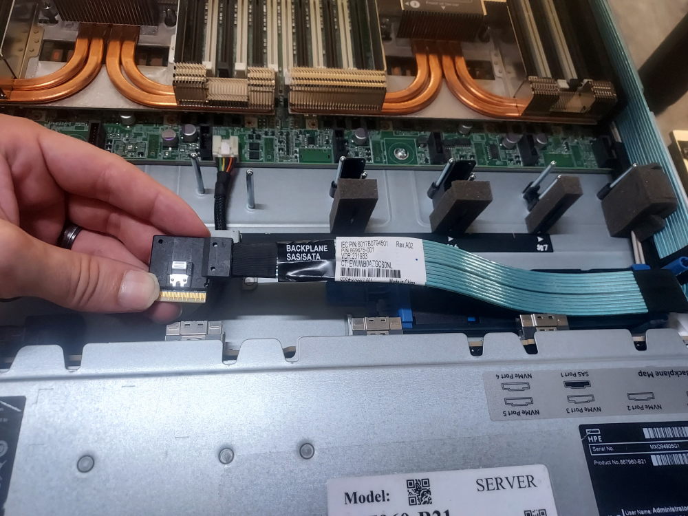
This is the the backplane for the 12 bay configuration. If you will be using a mini mono controller you’ll need this cable. If you’re using a PCIe controller you’ll need dell part number 0787PR. The backplane will also need the following signal cable and power cable. These cables connect it to the motherboard.
Click here for 24 bay configuration
The 24 bay SFF variation will of course have its own backplane and also different cables that will connect it to the motherboard and storage controller. Make sure the backplane is present. If you have a mini mono storage controller this is the cable you’ll need. If you have a PCIe controller you’ll need this one. Be sure both the BP signal cable and the BP power cable are present and attached from the backplane to the motherboard.
Cooling
The Dell PowerEdge R740xd uses a combination of hot-swappable fan modules, processor heatsinks, and an air shroud to maintain proper operating temperatures throughout the chassis. These components work together to move air through the server and remove heat from the processors, memory, storage controllers, PCIe cards, and other heat-producing hardware.
The exact cooling requirements depend on how the R740xd is configured. Processor TDP, storage configuration, PCIe expansion cards, and the installation of additional storage such as a rear flex bay can all affect the thermal requirements of the system.
Fan Modules
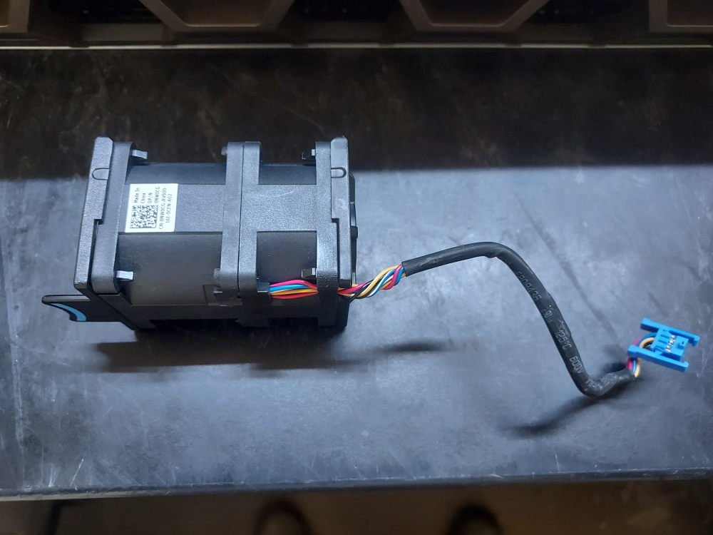
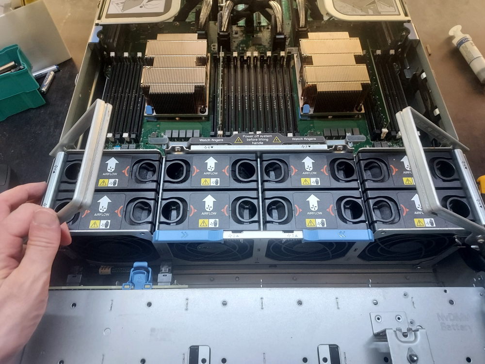
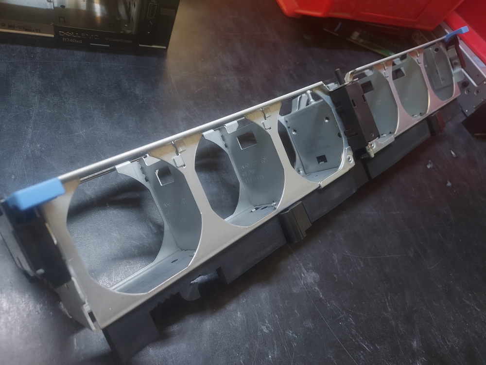
The fan modules are the primary active cooling components in the R740xd. The individual fans install into an assembly cage, which is then installed into the chassis as a complete unit. Like other Dell PowerEdge systems, the R740xd uses orange fan housings to identify hot-swappable components.
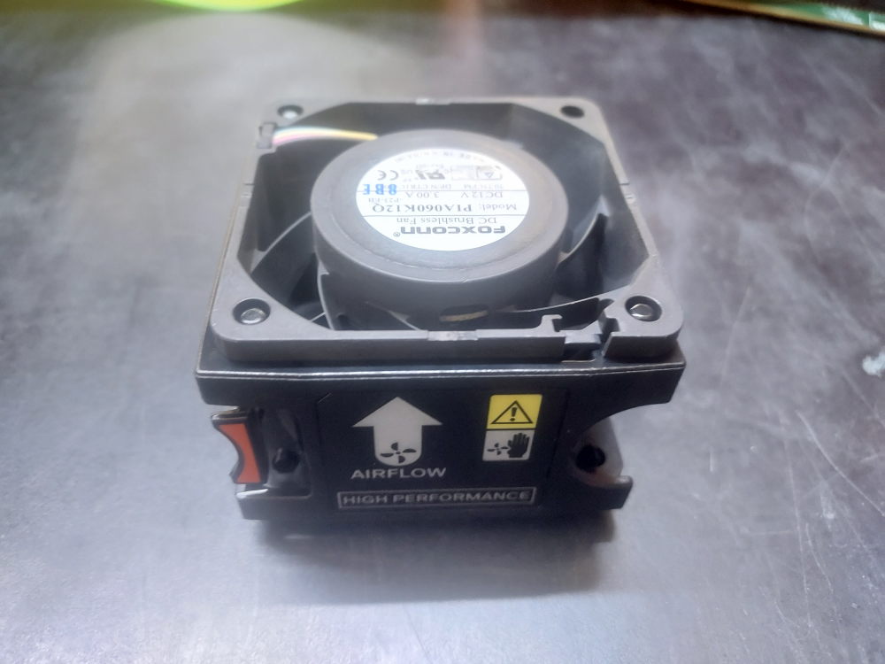
The R740xd is available with both standard-performance and high-performance fan modules. The appropriate fan configuration depends on the processors and other hardware installed in the server.
High-performance fans may be required when the system is equipped with higher-TDP processors or other hardware that generates additional heat. Certain R740xd storage and expansion configurations can also increase the cooling requirements. For example, configurations using a rear flex bay require high-performance fans.
When building an R740xd from an empty chassis, the fan type should therefore be determined from the complete hardware configuration rather than from the chassis alone. Installing standard-performance fans in a configuration that requires high-performance cooling can cause the fans to operate at higher speeds and may result in increased noise or thermal warnings.
Number of Fan Modules
The R740xd uses six fan modules as its primary chassis cooling system. All six fan positions should be populated for normal operation.
The server monitors the fan modules and adjusts fan speed according to the thermal requirements of the system. Missing or incorrectly installed fans can result in system warnings, logged hardware events, and increased fan speeds from the remaining modules. Before powering on a completed R740xd build, verify that all six fan modules are installed and properly seated.
Processor Heatsinks
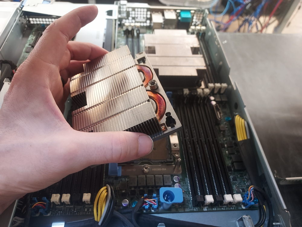
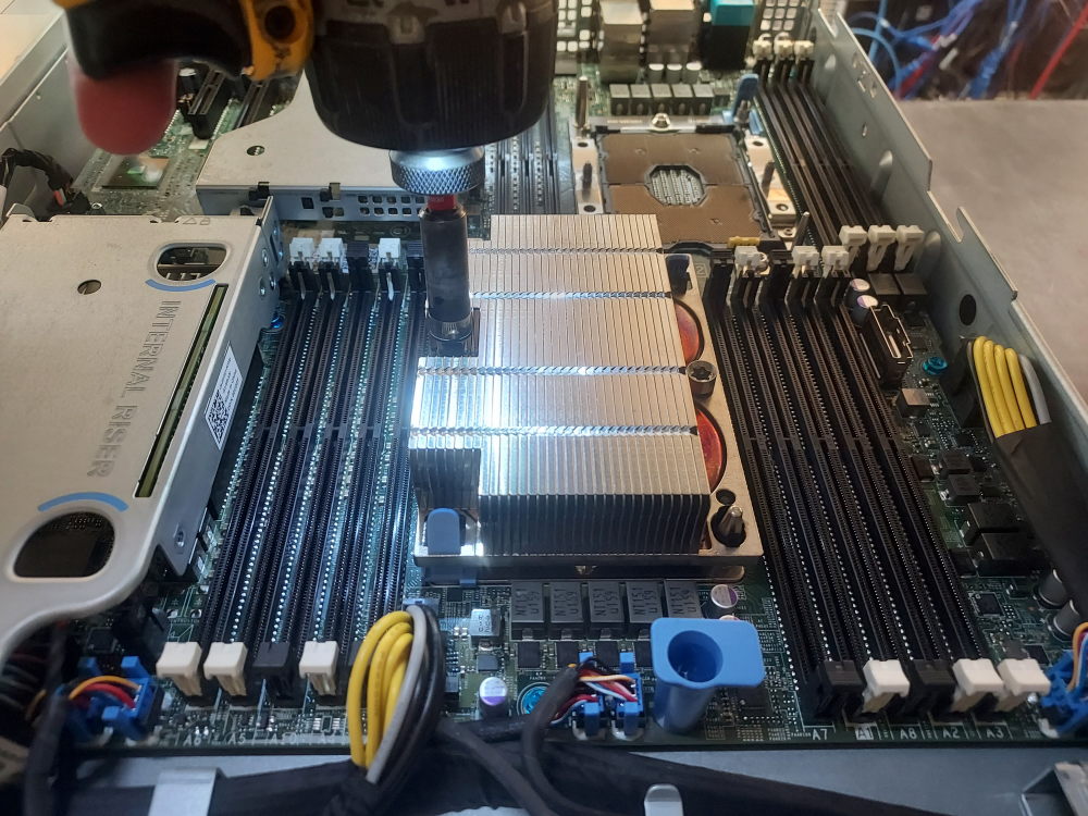
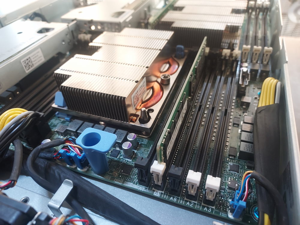
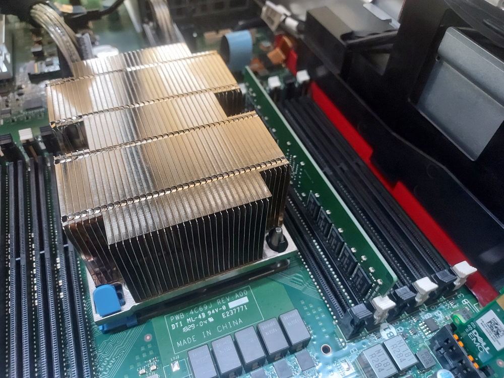
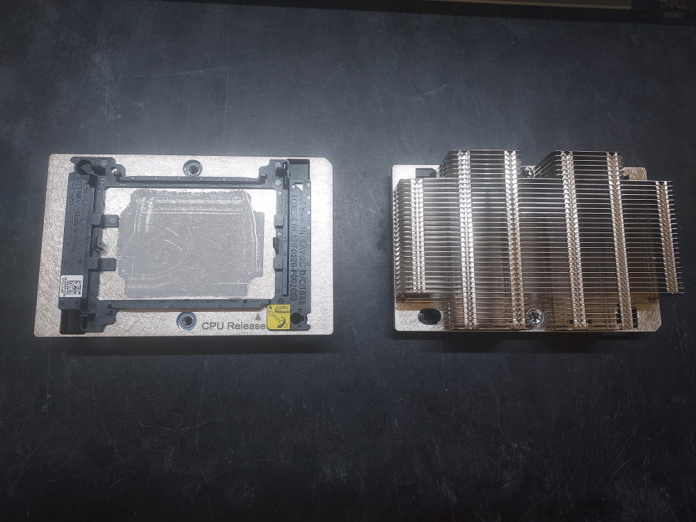
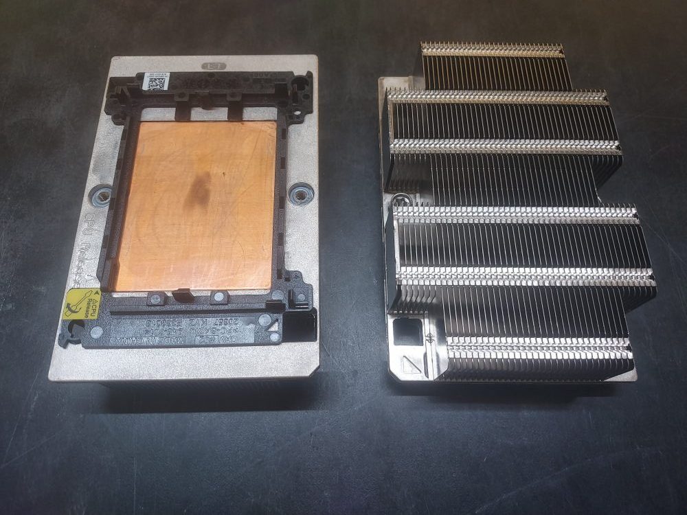
Each installed processor requires a compatible heatsink. A two-processor R740xd therefore requires two heatsinks. Dell offered both 1U standard-performance and high-performance heatsinks, along with a larger 2U high-performance heatsink designed specifically for the R740/R740xd platform.
Standard heatsinks are lower-profile aluminum designs, while high-performance heatsinks provide greater thermal capacity and use a copper contact surface to improve heat transfer from the processor.
The heatsink must be matched to the processor and overall system configuration. Higher-TDP processors may require a high-performance heatsink and corresponding fan configuration.
Each heatsink also includes a black plastic retention clip on its underside. The clip helps secure the processor against the heatsink and maintains the proper position during installation. The retention clip is part of the heatsink assembly and should remain installed.
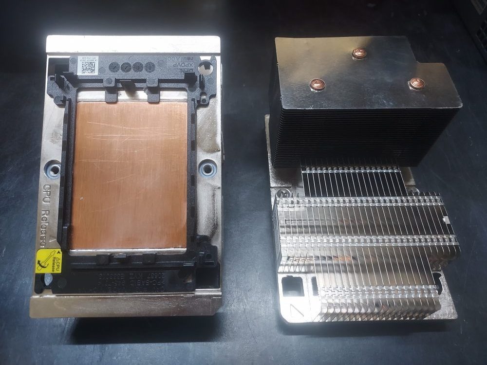
The R740xd can use three general heatsink configurations: standard-performance 1U heatsinks, high-performance 1U heatsinks, and the larger 2U high-performance heatsink. Certain storage configurations may require the 1U low profile heatsinks. For example, the installation of a midbay is not possible with 2U heatsinks so the 1U variation must be used instead.
Click to see standard-performance 1U heatsinks
Click to see high-performance 1U heatsinks
Air Shroud
The final major component of the R740xd cooling system is the air shroud. The shroud sits over the motherboard and directs airflow from the fan assembly through the areas containing the processors, memory modules, and other heat-producing components.
The air shroud is an important part of the server’s thermal design. Operating the R740xd without the shroud can disrupt the intended airflow path and reduce cooling performance. It should therefore be installed before normal operation of the server. A mid bay will require the removal of the air shroud.
Servers configured with a GPU will use a different air shroud.
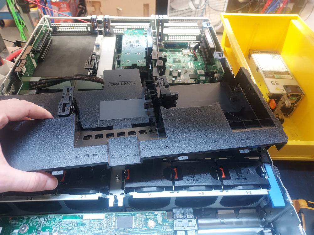
The fan modules, processor heatsinks, and air shroud work together as a complete thermal-management system. Before powering on an R740xd assembled from an empty chassis, verify that the appropriate fan modules and heatsinks are installed, all fan positions are populated, and the air shroud is securely in place.
Risers
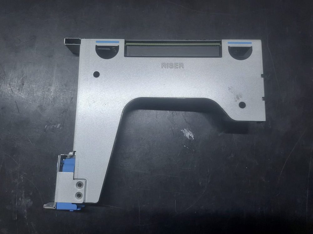
The R740xd supports a wide range of PCIe riser configurations. Several riser positions are available, and some positions have multiple variations that provide different combinations of PCIe slot width, physical card height, and card length.
The correct riser configuration depends on the hardware being installed in the server. A particular riser may provide additional PCIe slots but may also interfere with other components or storage options. This is especially important on the R740xd because configurations such as rear flex bays can occupy space that would otherwise be available for certain risers.
Riser selection can also affect the installation of storage controllers, network adapters, HBAs, GPUs, and other PCIe expansion cards. Some riser variations provide only low-profile slots, while others provide full-height slots capable of accepting larger expansion cards.
| Expansion Card Riser | PCIe Slot | Height | Length | Link |
|---|---|---|---|---|
| Riser 1A | Slot 1 | Full Height | Full Length | x16 |
| Slot 3 | Full Height | Half Length | x16 | |
| Riser 1B | Slot 1 | Full Height | Full Length | x8 |
| Slot 2 | Full Height | Full Length | x8 | |
| Slot 3 | Full Height | Half Length | x8 | |
| Riser 1D | Slot 1 | Full Height | Full Length | x16 |
| Slot 2 | Full Height | Full Length | x8 | |
| Slot 3 | Full Height | Half Length | x8 | |
| Riser 2A or 2E | Slot 4 | Full Height | Full Length | x16 |
| Slot 5 | Full Height | Full Length | x8 | |
| Slot 6 | Low Profile | Half Length | x8 | |
| Riser 2B | Slot 4 | Low Profile | Half Length | x8 |
| Riser 2C | Slot 4 | Low Profile | Half Length | x16 |
| Riser 3A or 3B | Slot 7 | Full Height | Full Length | x8 |
| Slot 8 | Full Height | Full Length | x16 |
Riser 1
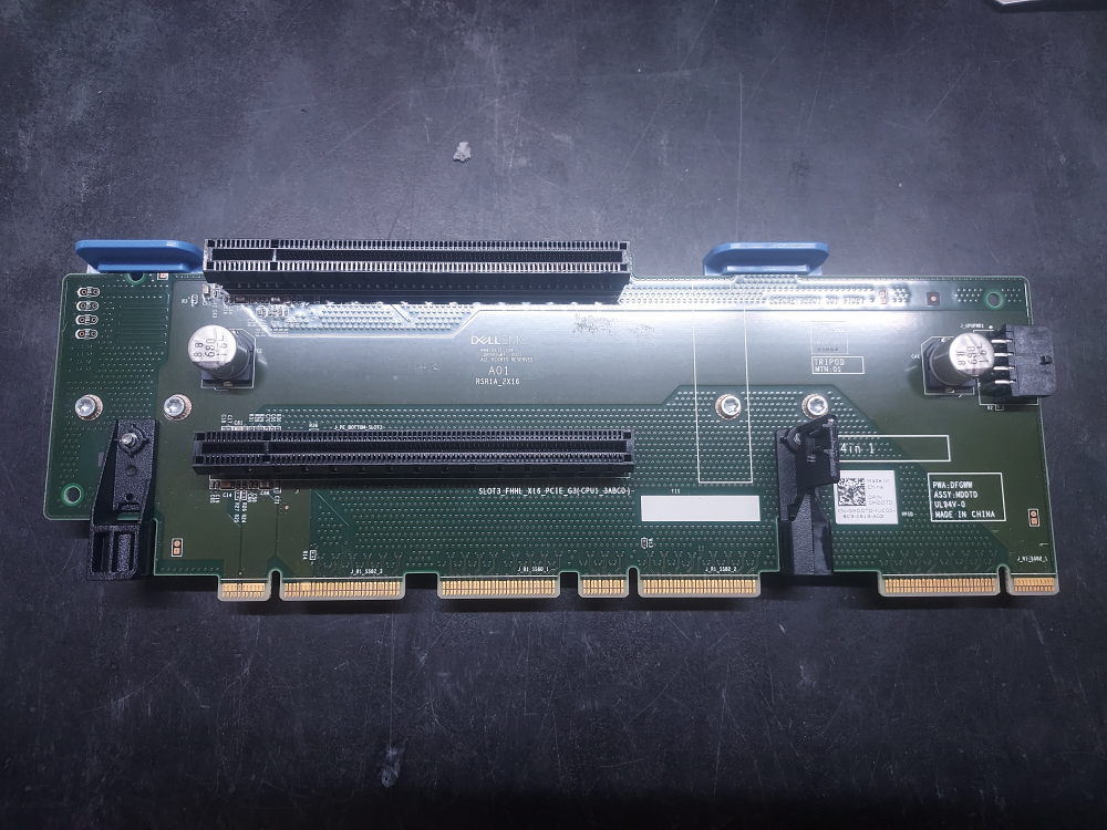
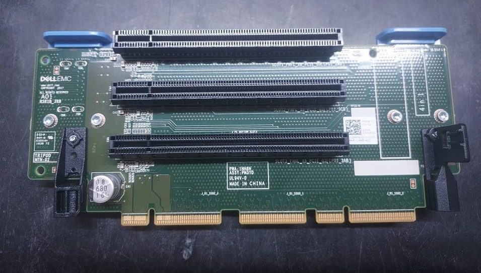
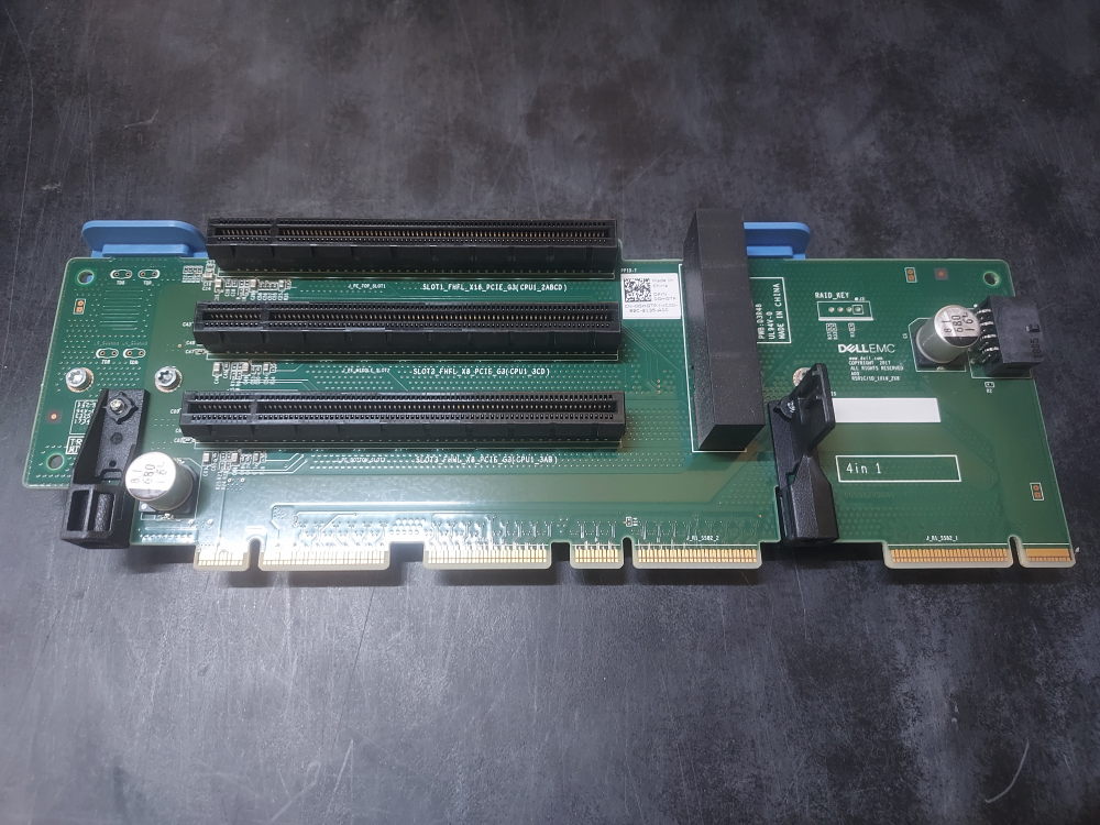
The R740xd can use several variations of Riser 1. Riser 1A, 1B, and 1D provide different combinations of PCIe slot widths and should be selected according to the expansion cards being installed.
Riser 1A
Click to see Riser 1B
Click to see Riser 1D
Riser 2
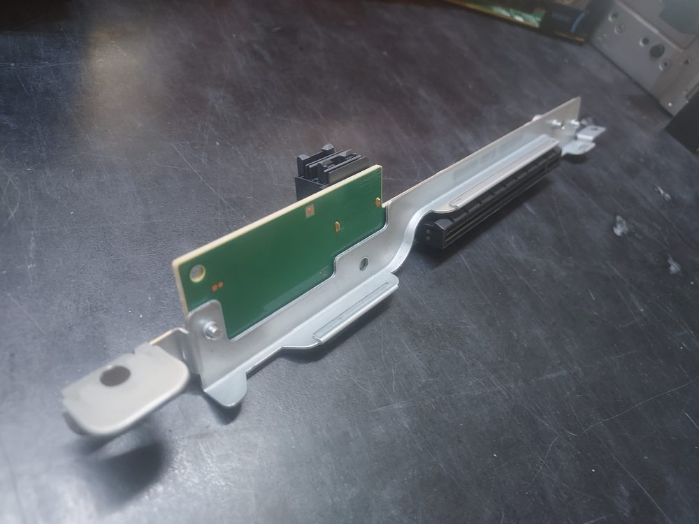
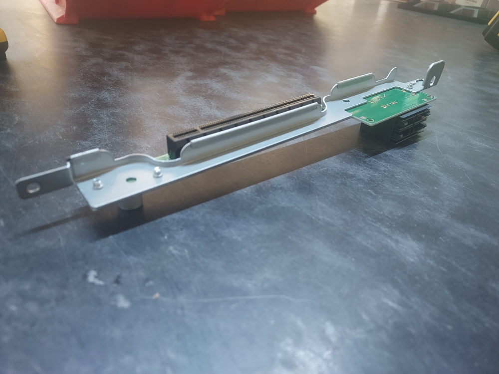
Riser 2 is available in several configurations, including full-height Riser 2A/2E and low-profile Riser 2B and 2C configurations.
Riser 2A/2E provides three expansion slots, including two x8 slots and an x16 slot. This is the full-height option and is suitable when the available chassis space allows the installation of full-height expansion cards.
The low-profile Riser 2B and 2C configurations provide an alternative when chassis space is limited or when another component occupies the area normally used by the full-height riser. This is particularly relevant on the R740xd when installing certain rear storage or flex-bay configurations.
When selecting a Riser 2 configuration for an R740xd build, consider the complete hardware configuration rather than selecting the riser solely based on the number of PCIe slots it provides. Storage expansion, rear flex bays, PCIe cards, and card height can all affect which Riser 2 configuration can be installed.
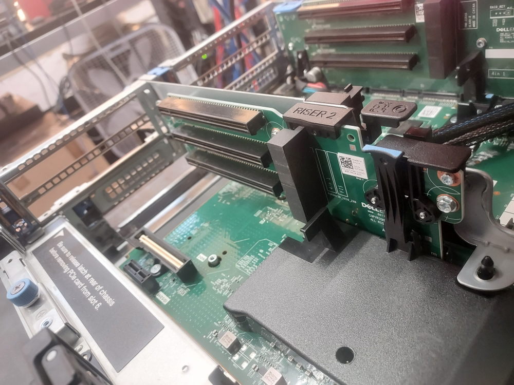
Click to see Riser 2B
Click to see Riser 2C
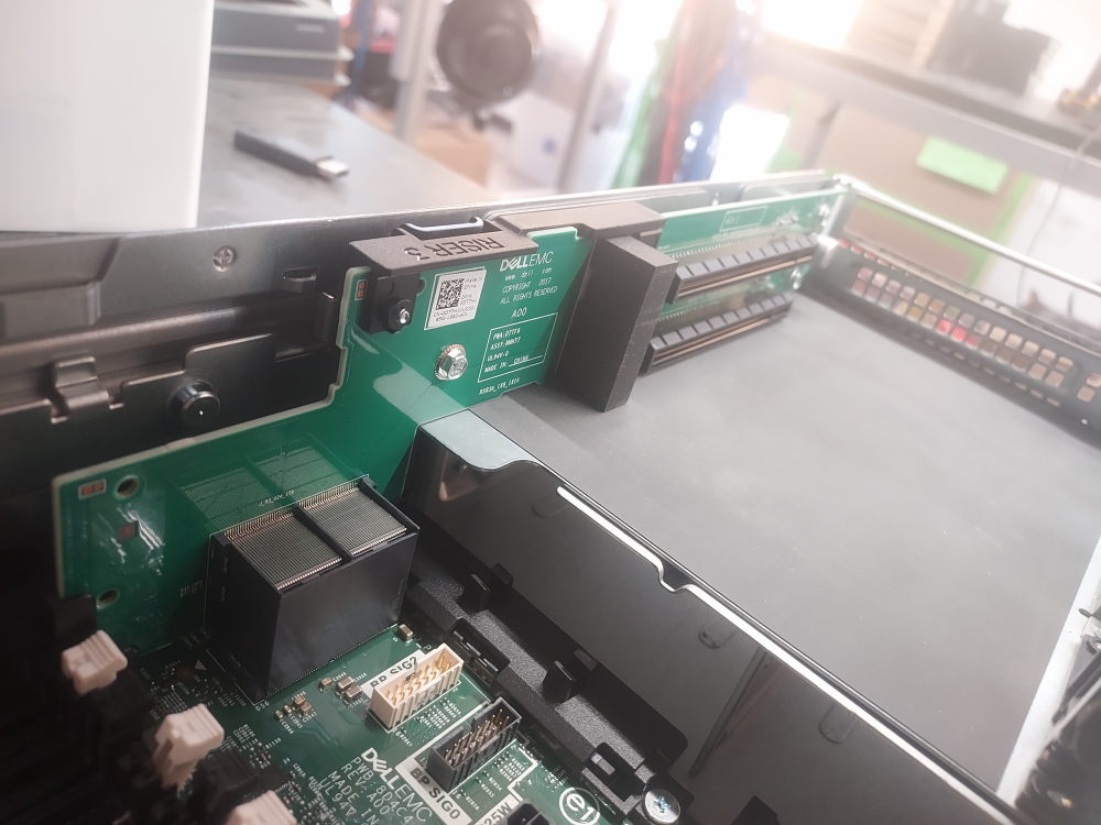
Riser 3A and 3B
Riser 3 provides two additional PCIe slots at the rear of the server. The available slots provide different PCIe link widths, with Slot 7 providing an x8 connection and Slot 8 providing an x16 connection.
Building the Server
Once you have confirmed that the R740xd chassis contains the required hardware, you can begin assembling the system. Before installing every component, it is useful to perform an initial power-on test using only the hardware required for the server to complete POST.
This approach makes troubleshooting easier because there are fewer components to check if the server fails to start or reports a hardware error.
At a minimum, the system will need:
- At least one compatible CPU
- At least one compatible memory module
- At least one power supply
Additional hardware such as the storage backplane, PERC or HBA controller, PCIe risers, network adapters, and storage drives can then be installed and tested as the build progresses.
Required Tools
Tools needed to build a Dell PowerEdge R740xd
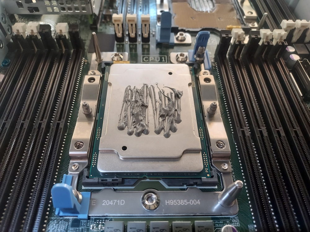
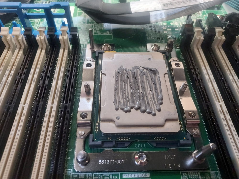
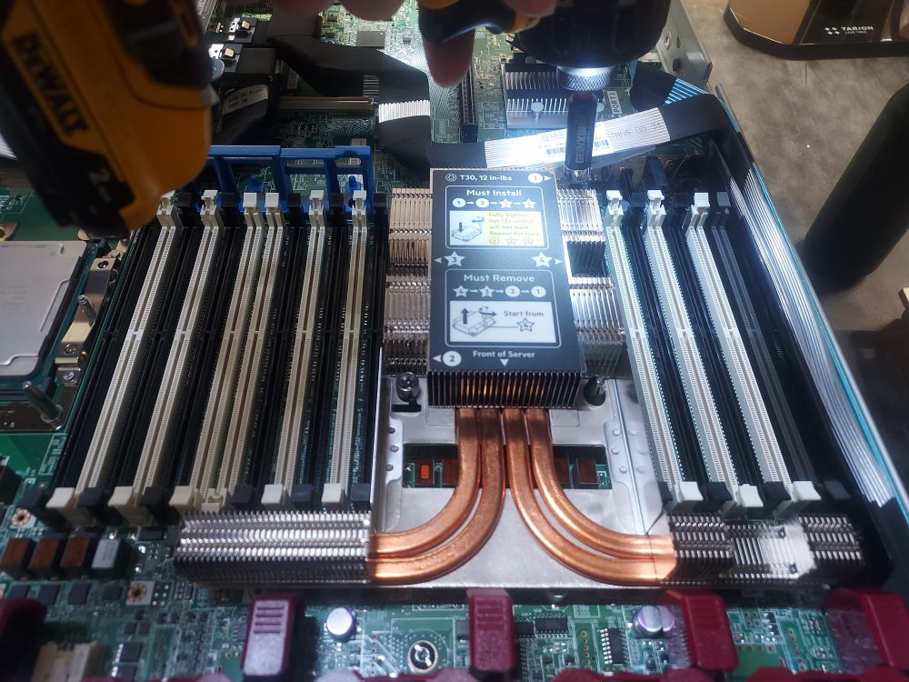
Fortunately, assembling a Dell PowerEdge R740xd does not require a large collection of specialized tools. Before beginning the build, you should have a Phillips #2 screwdriver, a T30 Torx bit, thermal paste, and either an electric air blower or a can of compressed air available.
The R740xd can operate with a single processor, but doing so limits some of the server’s functionality. Certain PCIe slots and other system resources are connected to CPU2 and will not be available when the second processor is not installed. If you plan to install additional PCIe expansion cards, verify the slot configuration and CPU requirements before deciding to build the server with only one processor.
Installing the Processors
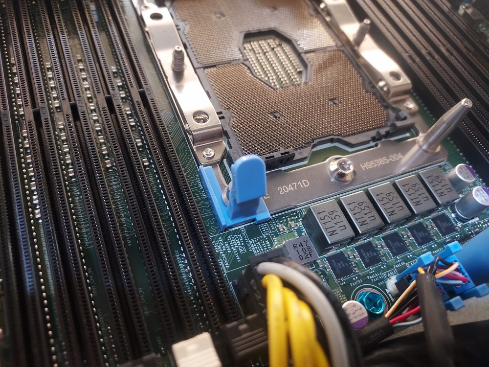
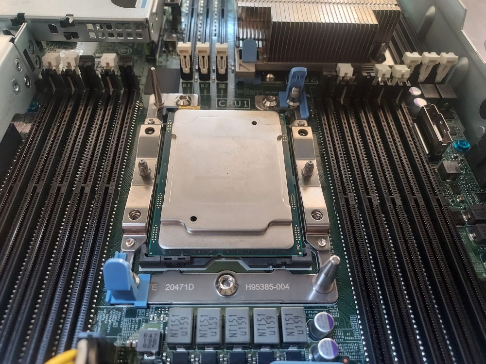
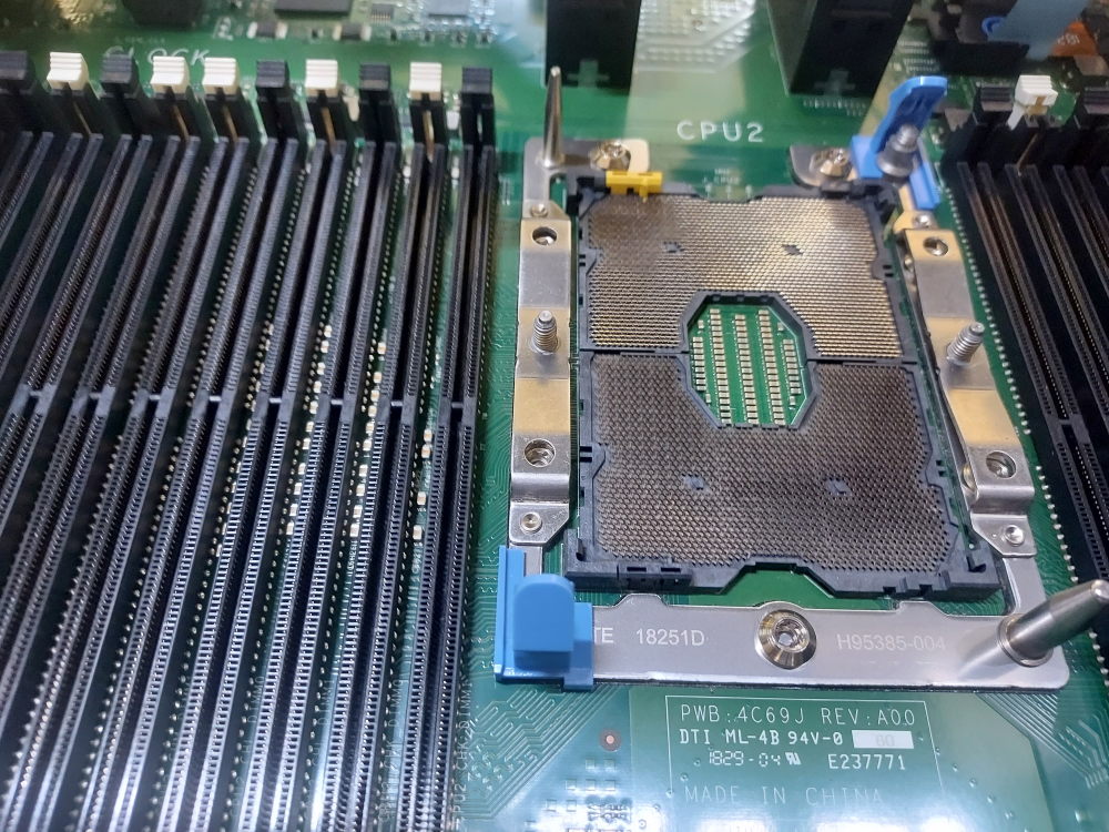
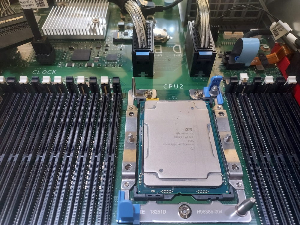
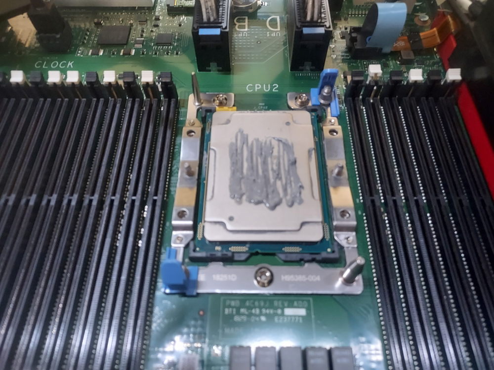
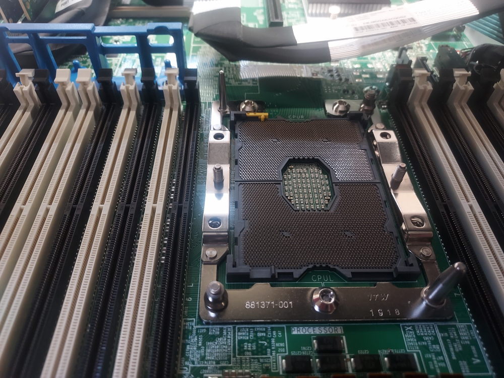
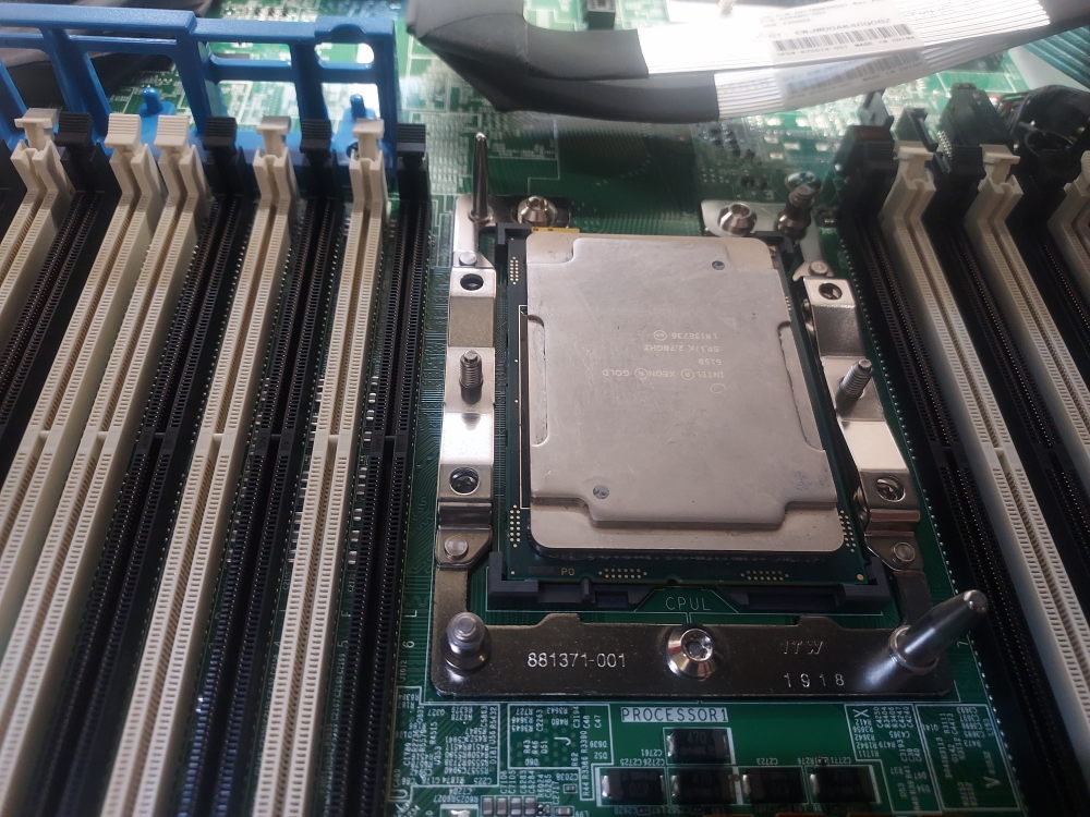
The R740xd has two processor sockets located near the center of the motherboard, identified as CPU1 and CPU2. Depending on the condition of the chassis, the sockets may already contain processors and heatsinks, or they may be covered by protective CPU socket covers.
If you are installing a processor into a previously used system, first remove the existing heatsink and processor if necessary. If the socket is empty, remove the protective socket cover before installing the CPU. Pay close attention to the orientation markings on both the processor and socket. The processor can only be installed in one orientation. Attempting to install it incorrectly can damage the delicate socket contacts and potentially render the motherboard unusable.
Before installing the processor, inspect the socket and remove any dust or debris using compressed air or an electric air blower. Avoid touching the socket contacts.
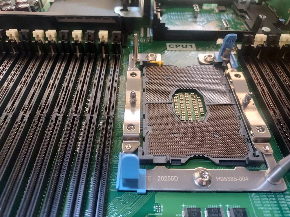
Take particular care when working around the processor sockets. The contacts inside the LGA socket are extremely delicate and can be bent by improper handling. Hold the processor by its edges and make sure it is correctly oriented before lowering it into the socket.
You can also install the CPU onto the heatsink first. This is the often recommended approach. I do take some issue with this method. Having built thousands of servers I’ve seen the black plastic retainer clips become brittle over time from years of heat exposure. Unless the retainer clip is brand new I would not trust it to properly secure the CPU into place. If you flip it over there’s a good chance the CPU comes right out of the clips – potentially damaging the CPU or worse yet – the pins on the socket itself.
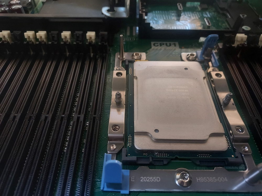
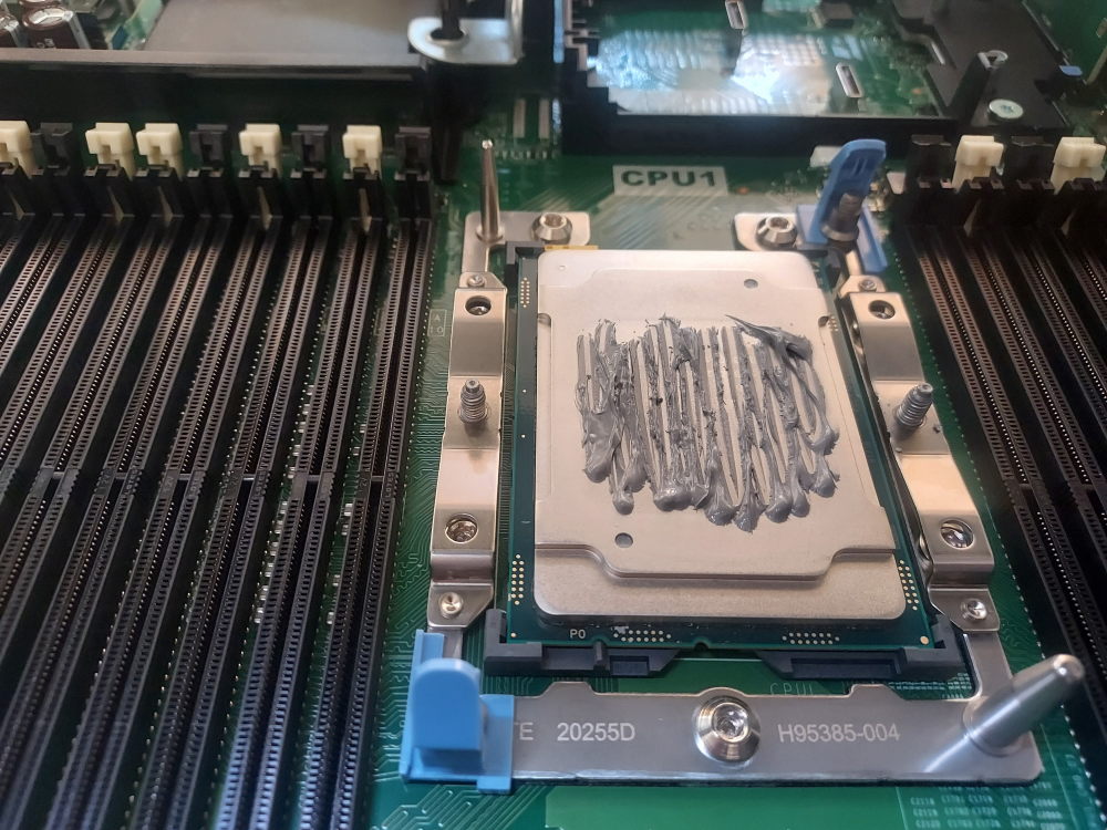
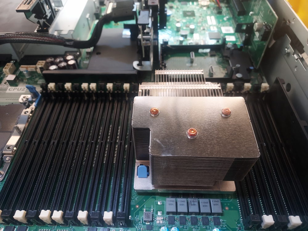
If you are building a dual-processor system, repeat the procedure for CPU2. Both processors should be from the same supported processor generation and should be installed according to Dell’s processor compatibility requirements.
Installing the Memory
The R740xd has six memory channels per processor, with two DIMM slots available on each channel. A system with two processors therefore has 24 DIMM slots in total, with 12 slots assigned to each processor.
The DIMM slots are arranged into primary and secondary positions. The primary slots (the white slots) should be populated before the secondary slots. When installing memory, use the appropriate primary DIMM locations for the number of modules being installed rather than simply filling the slots from left to right.
For best memory performance, distribute DIMMs across as many memory channels as possible. In a dual-processor system, memory should also be distributed evenly between CPU1 and CPU2 whenever practical.
For example, if you have four identical DIMMs to install in a dual-processor R740xd, a balanced configuration is to install two DIMMs on CPU1 and two DIMMs on CPU2, using the primary memory slots. In this configuration, the DIMMs would be installed in A1, A2, B1, and B2.
Dell uses A to identify the memory slots associated with CPU1 and B to identify the slots associated with CPU2. If you have difficulty locating the DIMM slots, the memory layout is printed on your servers air shroud.
When adding memory to an existing configuration, try to maintain matching DIMM capacity, rank characteristics, speed, and memory type across corresponding channels. The R740xd supports DDR4 ECC RDIMMs and LRDIMMs, but RDIMMs and LRDIMMs should not be mixed within the same system.
Click here to view the R740xd memory channel mapping
| CPU (Socket) | Memory Channel | Primary DIMM (1 DPC) | Secondary DIMM (2 DPC) |
|---|---|---|---|
| Socket 01 (CPU1) | Channel 0 | A1 | A7 |
| Channel 1 | A2 | A8 | |
| Channel 2 | A3 | A9 | |
| Channel 3 | A4 | A10 | |
| Channel 4 | A5 | A11 | |
| Channel 5 | A6 | A12 | |
| Socket 02 (CPU2) | Channel 0 | B1 | B7 |
| Channel 1 | B2 | B8 | |
| Channel 2 | B3 | B9 | |
| Channel 3 | B4 | B10 | |
| Channel 4 | B5 | B11 | |
| Channel 5 | B6 | B12 |
For example, with four identical DIMMs, two modules can be installed on CPU1 in A1 and A2, while the other two are installed on CPU2 in B1 and B2. This distributes the memory evenly between the two processors while using the primary DIMM positions.
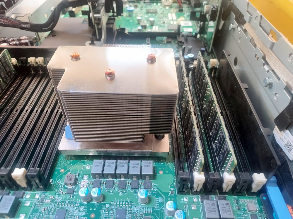
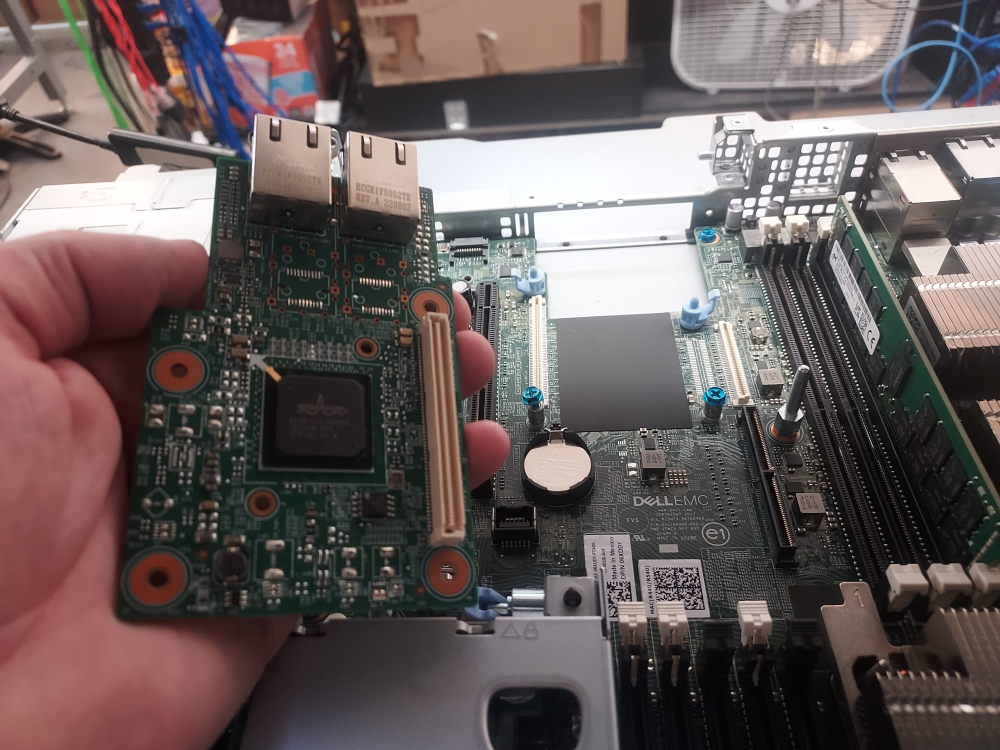
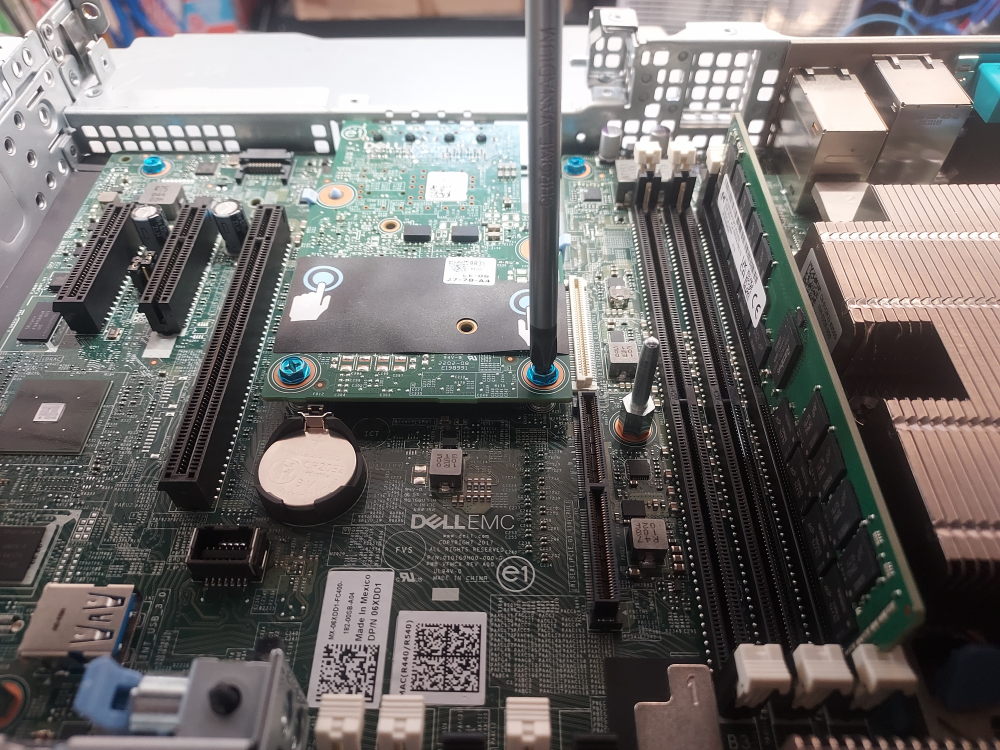
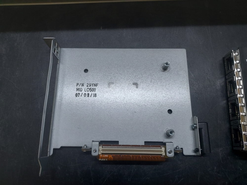
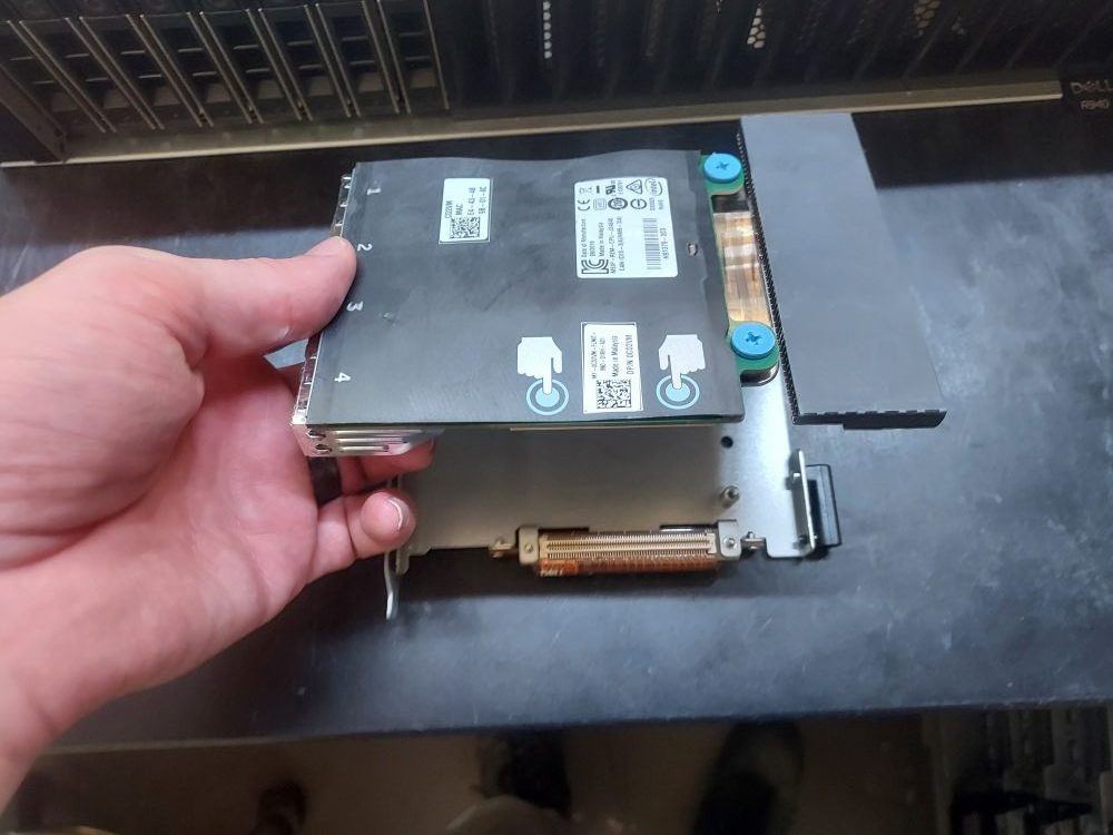
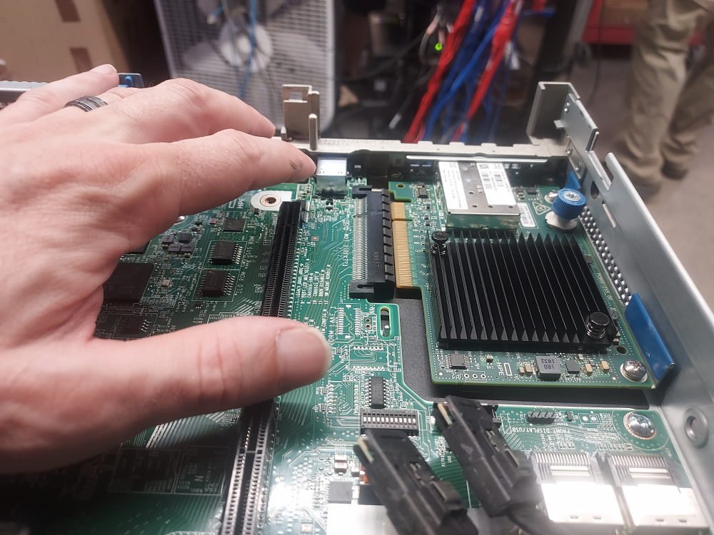
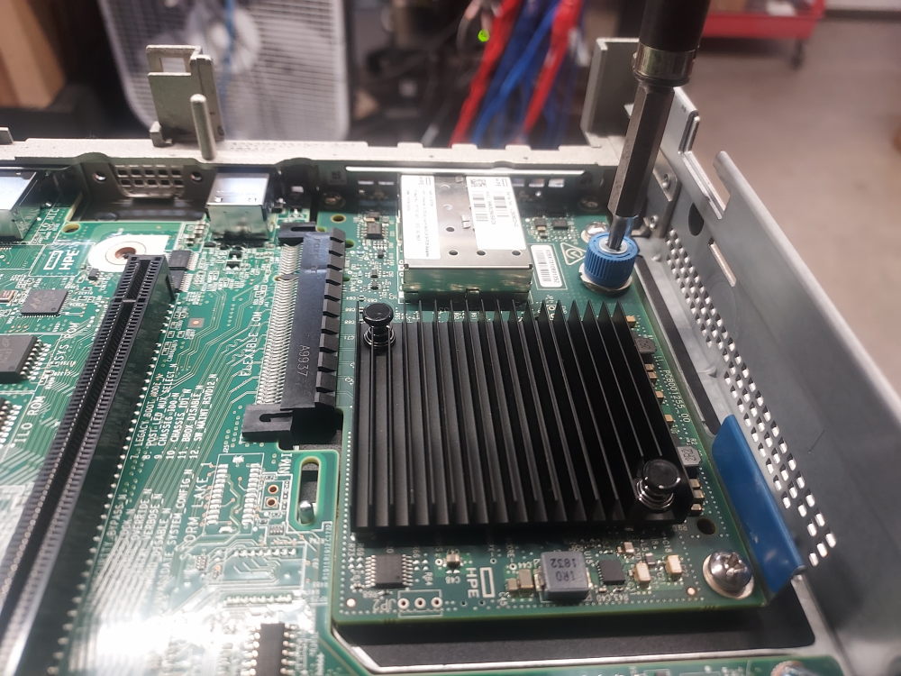
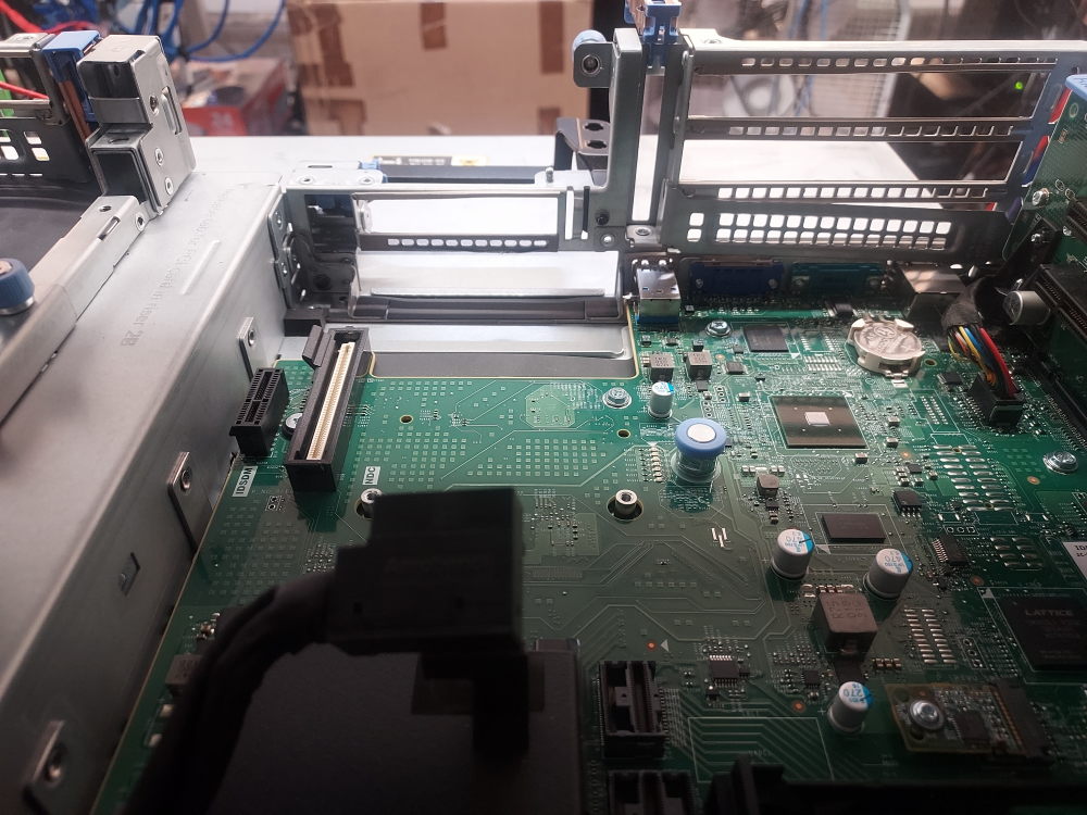
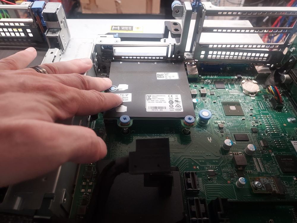
Installing the NDC
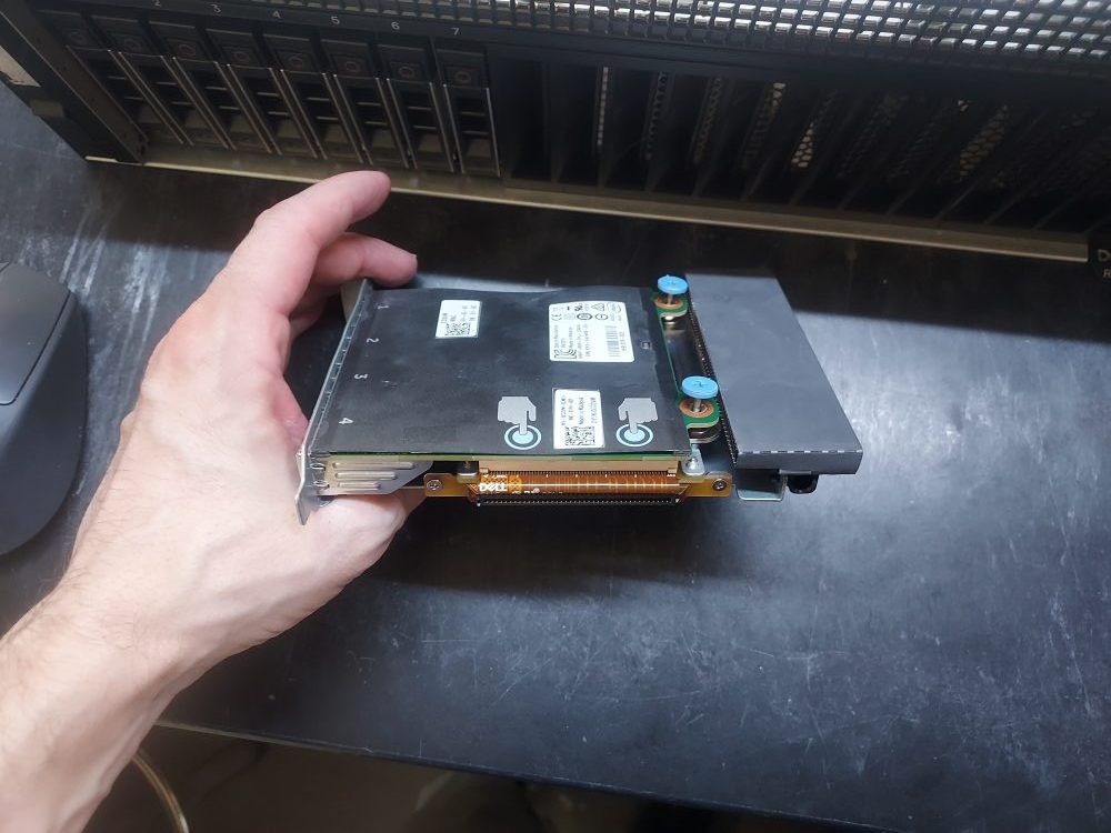
The Network Daughter Card (NDC) provides the R740xd with its integrated network interfaces. Dell offered several NDC options with different port types and network speeds, so the exact interfaces available depend on the NDC installed in the server.
The installation procedure is the same for the different NDC options.
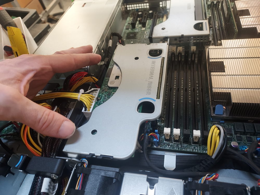
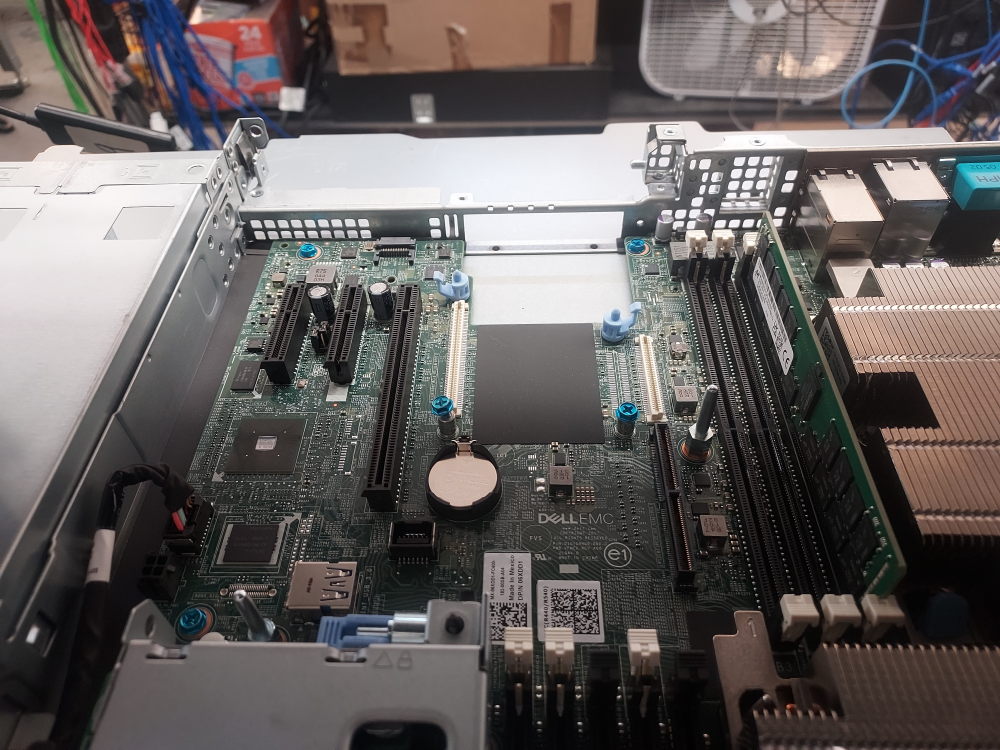
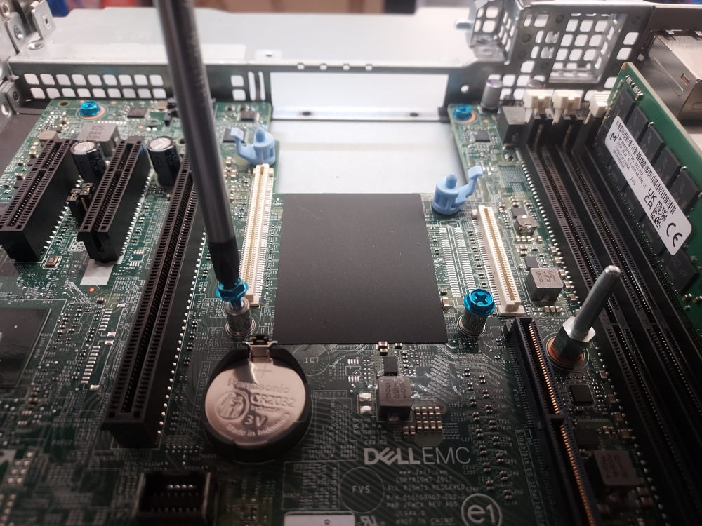
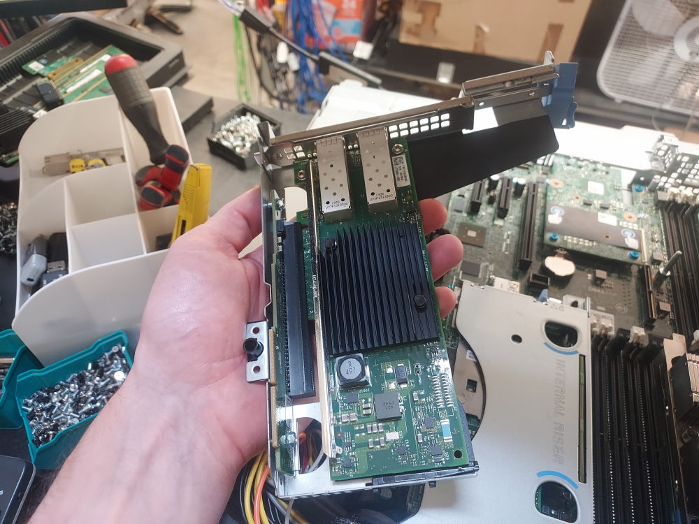
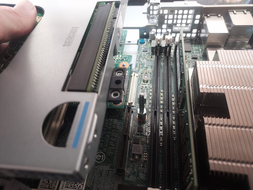
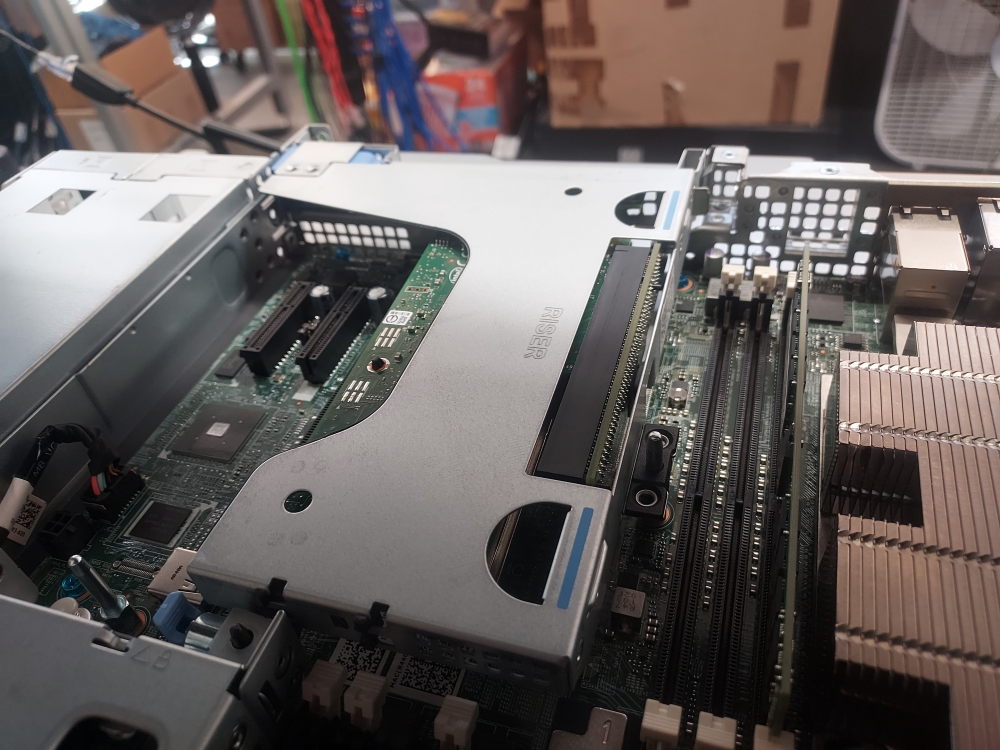
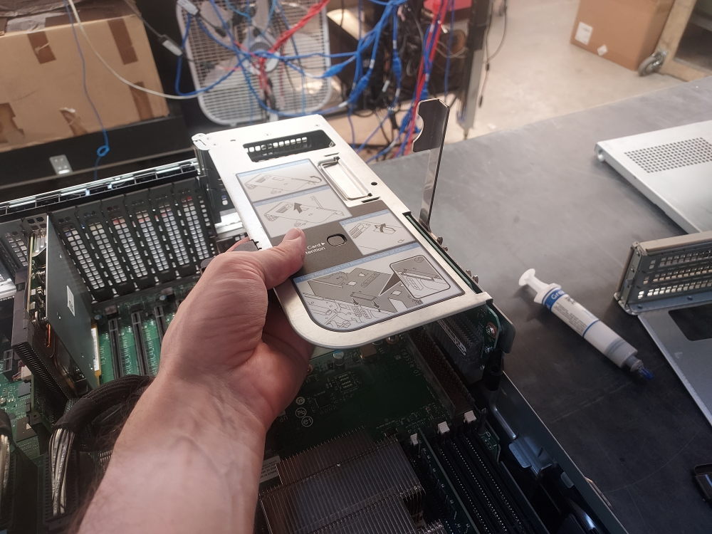
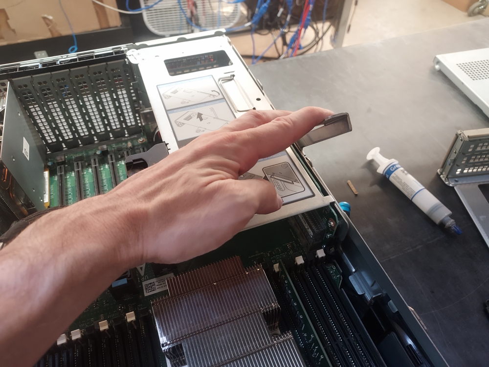
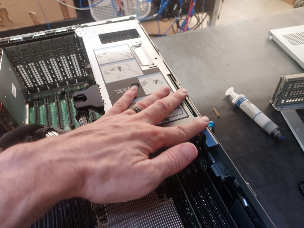
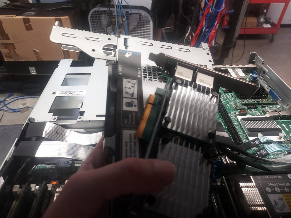
Begin by removing Riser 2. Removing the riser provides access to the proprietary Dell mezzanine connector used by the NDC.
Installing a RAID or HBA Controller
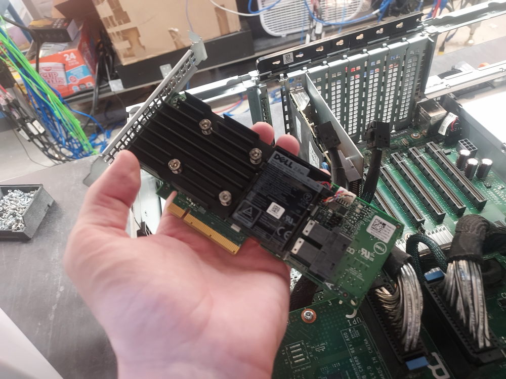
If you are installing storage drives in the R740xd, you will generally need a compatible RAID controller or HBA to connect the drives to the operating system. The exact controller and cabling requirements depend on the storage configuration and backplane installed in the server.
An HBA normally presents the physical drives directly to the operating system, leaving storage management to the operating system or storage software. A RAID controller, on the other hand, can combine physical drives into RAID virtual disks. Some Dell PERC controllers can also be configured for non-RAID or HBA-style operation, depending on the specific controller and firmware.
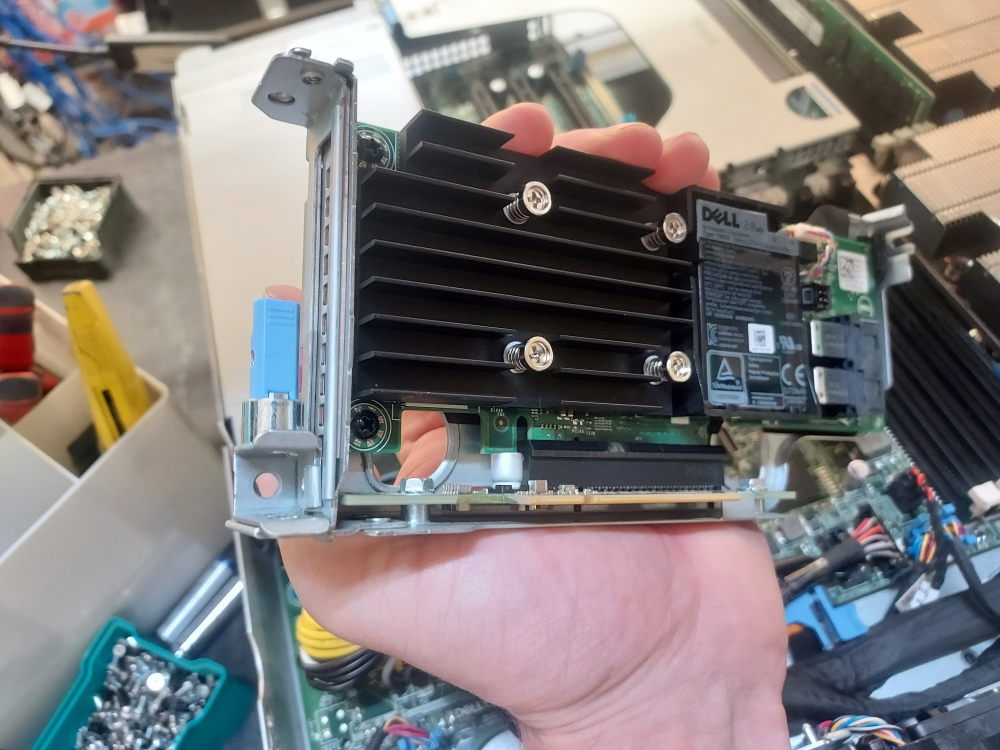
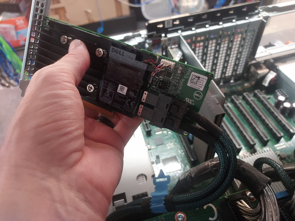
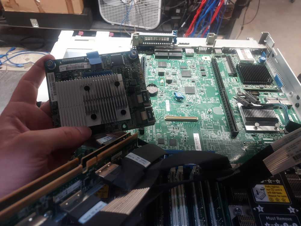
The R740xd can use both PCIe PERC/HBA controllers and Dell’s proprietary internal Mini PERC/Mini Mono controllers. Although both types ultimately provide access to the server’s storage devices, they connect to the system differently.
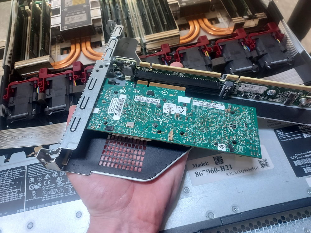
A PCIe controller is installed into one of the server’s PCIe risers. The appropriate riser and PCIe slot depend on the controller and the overall configuration of the R740xd.
The Mini PERC/Mini Mono controller uses a proprietary connection to the motherboard and therefore does not occupy a conventional PCIe expansion slot. This can be useful when the available PCIe slots are needed for network adapters, HBAs, GPUs, or other expansion cards. However, the Mini controller can impose restrictions on which riser configurations can be installed.
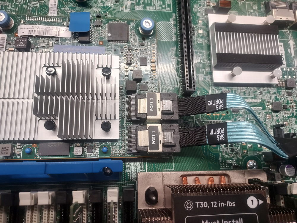
The storage backplane and SAS/PCIe cabling must match the controller and chassis configuration. The R740xd was produced in several storage configurations, including 12 × 3.5-inch LFF and 24 × 2.5-inch SFF configurations, as well as configurations with additional mid-bay, rear-bay, or NVMe storage. A cable that fits a connector is not necessarily the correct cable for a particular configuration.
For example, the 12 × 3.5-inch LFF configuration can use different SAS cables depending on whether the system uses a PCIe PERC, Mini PERC, or additional mid-bay storage. The 24 × 2.5-inch SFF configuration uses a different backplane and corresponding cabling. Verify the backplane, controller, and cable part numbers before installing the storage controller.
Click for PCIe RAID/HBA instructions
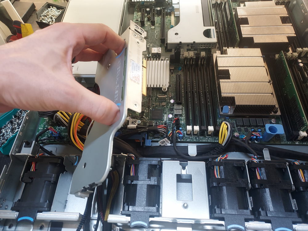
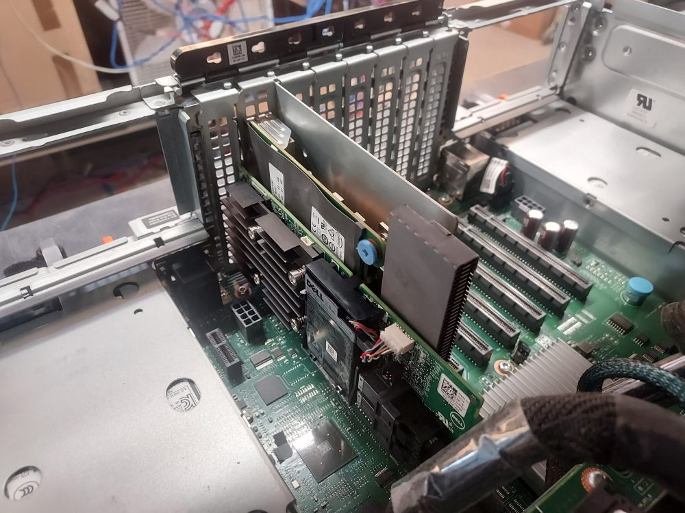
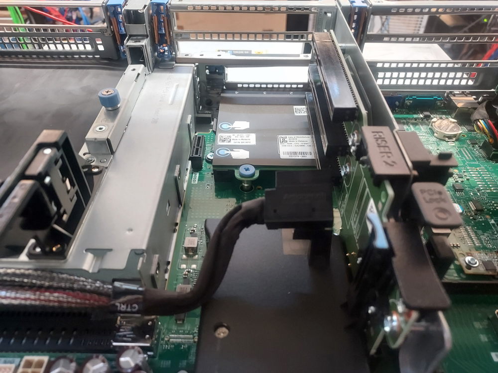 This is the PCIe installation area for the storage controller. If an NDC needs to be installed, install the NDC first because accessing the NDC requires removal of Riser 2. Before installing the controller, verify that the correct SAS cable for your R740xd backplane and storage configuration is routed to the controller location.
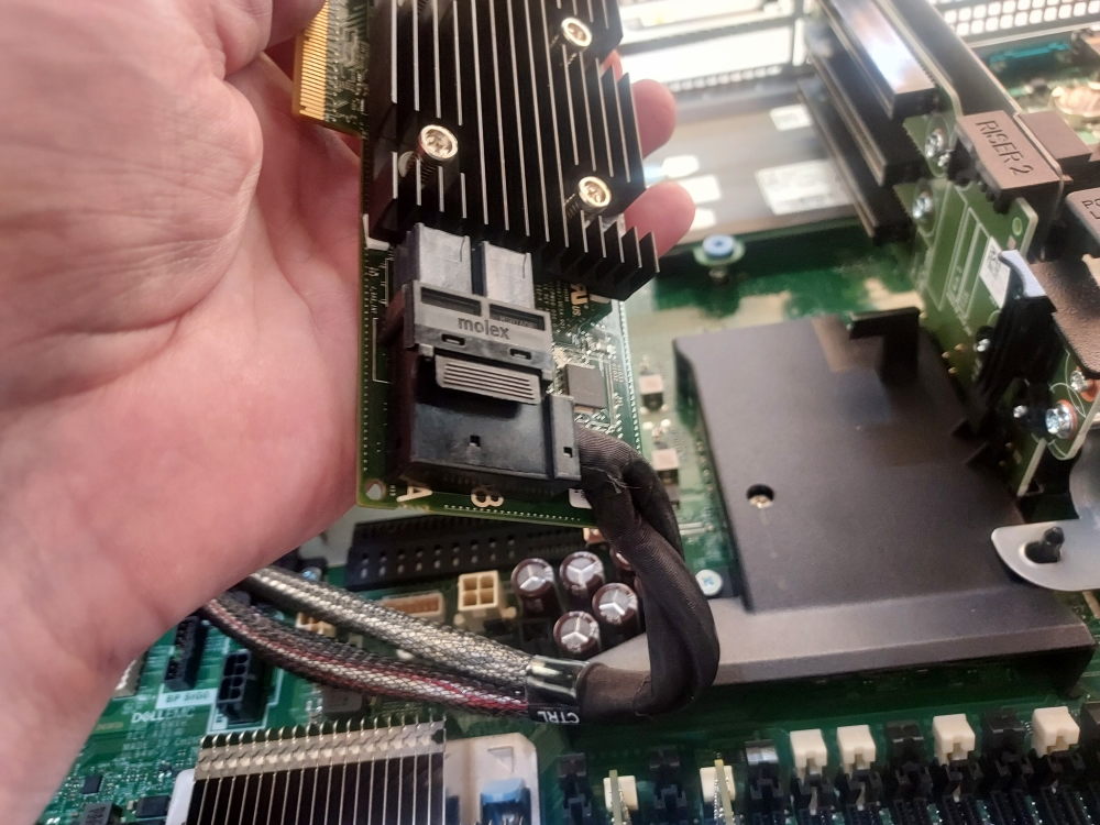 Connecting the storage cable to the controller before installing the controller into the PCIe slot can make installation easier, particularly when access to the connector is limited after the card is installed.
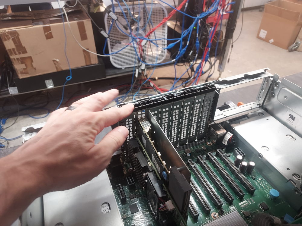
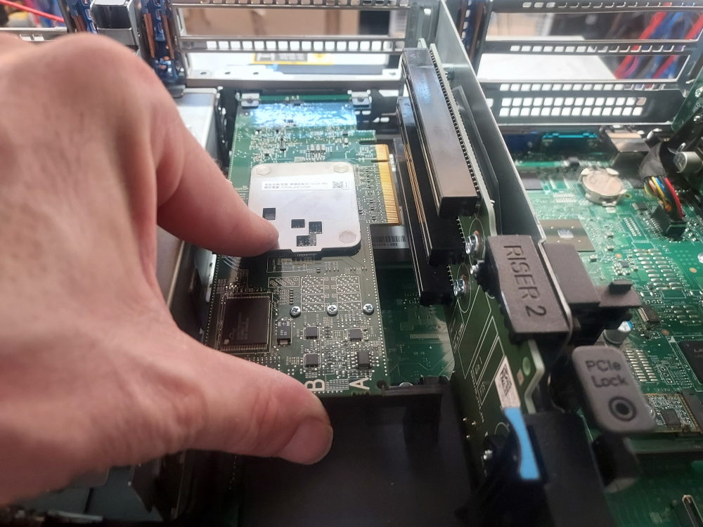 Align the controller with the appropriate PCIe slot. The exact slot depends on the riser installed in your R740xd configuration. Make sure the blue PCIe retention clip is in the outward position before inserting the card.
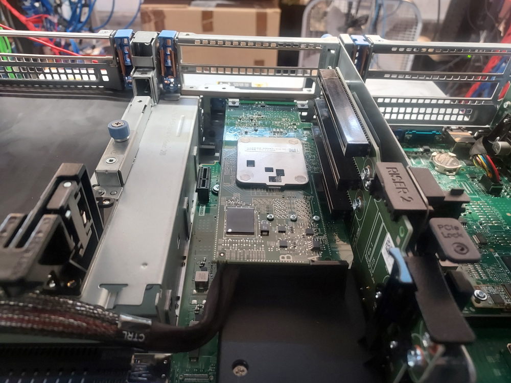 Firmly insert the controller into the PCIe slot and then return the blue retention clip to its locked position.
Click for Mini PERC/Mini Mono RAID/HBA instructions
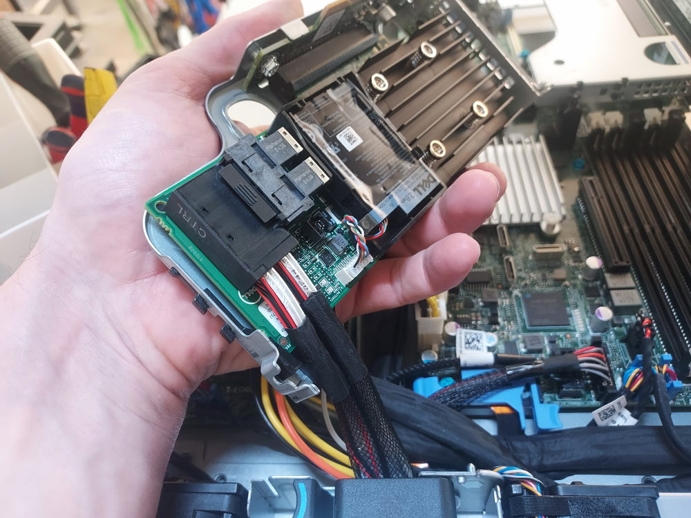
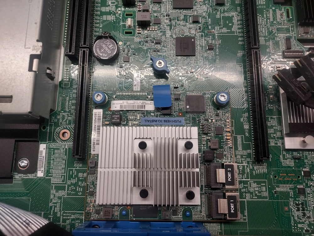
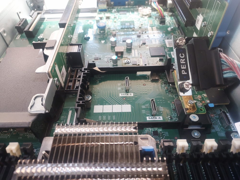 This is the installation point for the Mini PERC/Mini Mono storage controller. The proprietary interposer located beneath the PERC cable is required for compatible Mini PERC controllers. Because the Mini controller occupies space associated with certain riser configurations, verify riser compatibility before selecting this option.
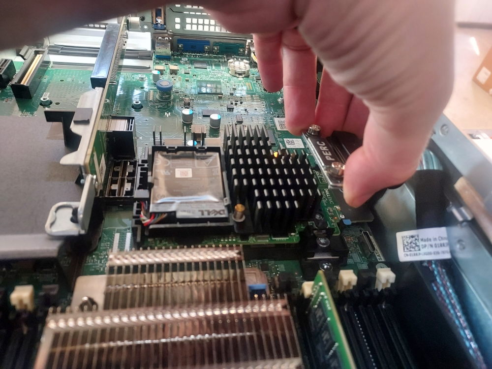 Slide the edge of the Mini PERC controller underneath the black plastic brackets and align the controller with the proprietary connector. Secure the storage cable to the controller contacts.
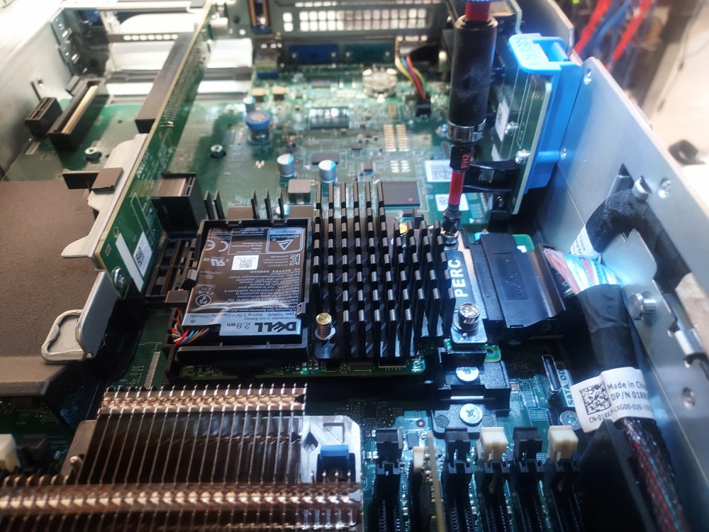 Secure the Mini PERC controller using the two mounting screws and a Phillips #2 screwdriver.
NVME configuration
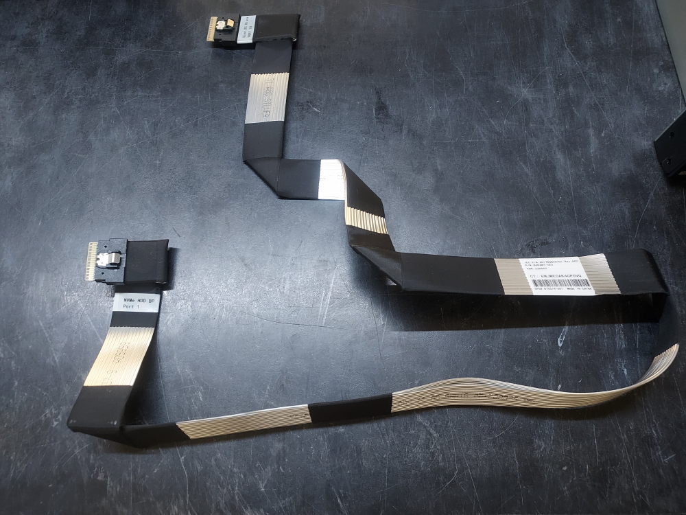
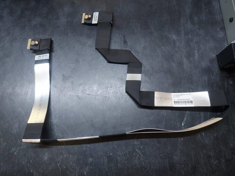
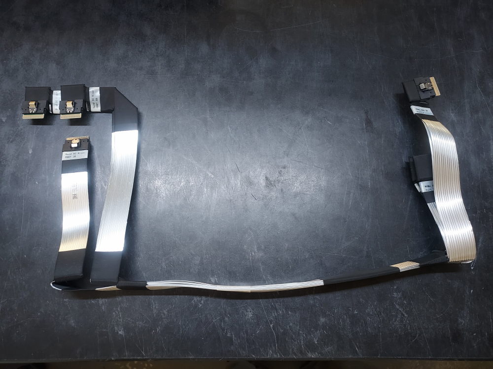
This is where the R740xd deviates from its R740 predecessor. The R740xd 24 bay supports up to 12 NVME drives with the proper cabling and NVME controllers.
Please note – NVME is only supported on the 24 bay chassis variation. The R740xd 12 bay backplane does not have the required connectors for NVME.
Click here for NVME configuration instructions
First make sure you have the 24 bay backplane otherwise none of the following steps are going to work. This particular configuration enables NVME support on the last 12 SFF drive bays of the 24 bay model.
To complete these steps you will need the following 3 cables:
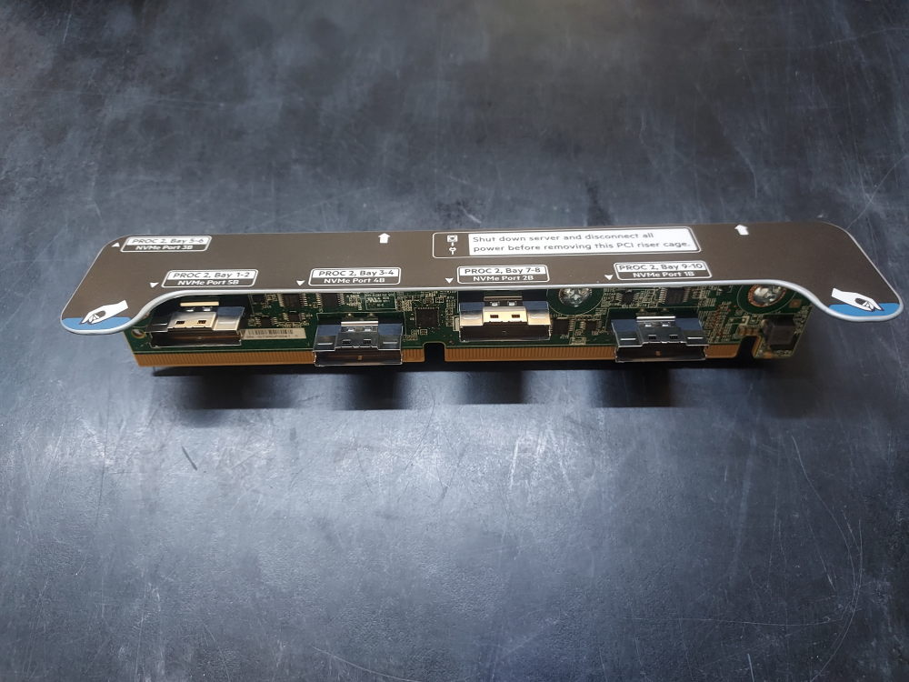
And 3 of the following NVME controllers:
As well as the following risers:
- Riser 1A or 1D
- Riser 2A
- Riser 3A
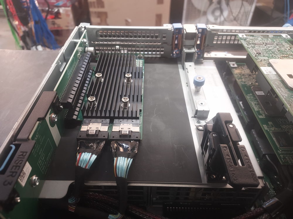
One end of the cable will connect to the backplane and then route to an NVME controller installed in a x16 slot in one of the risers. This is why it’s crucial to have the appropriate risers with the correct x16 slots installed.
The first cable will connect to ports A0/B0 on the backplane and route to an NVME controller in riser 1.
The second cable will connect to ports A1/B1 and connect to an NVME controller in riser 2.
The third cable will connect to ports A2/B2 and connect to an NVME controller in riser 3.
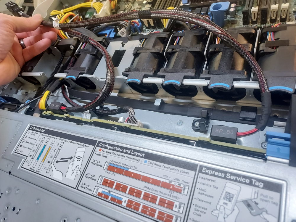
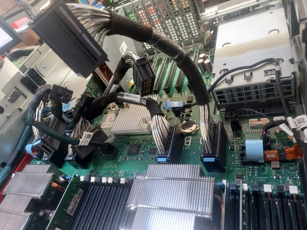
There are 6 connectors in total. Below you will see 4 of them. These are connectors A0/B0 and A1/B1. The connectors for A2/B2 are under the SAS expander and difficult to photograph. When cabling it helps to disconnect all other cables and physically remove the backplane from position. The cables are much easier to install if the backplane is slightly jostled out of place and at an angle. Reinstall the backplane once the cables are firmly connected.
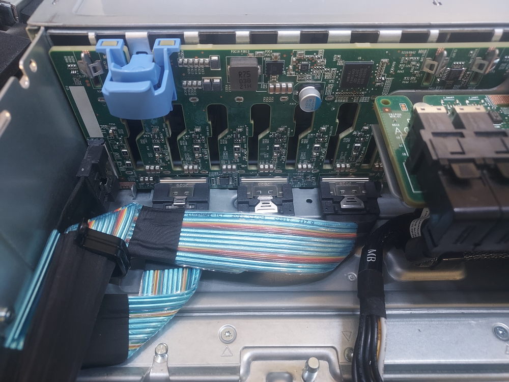
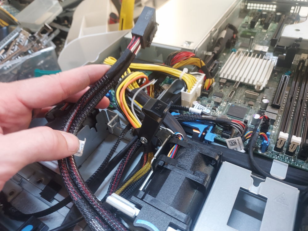
These cables will route along the right side of the chassis to the risers:
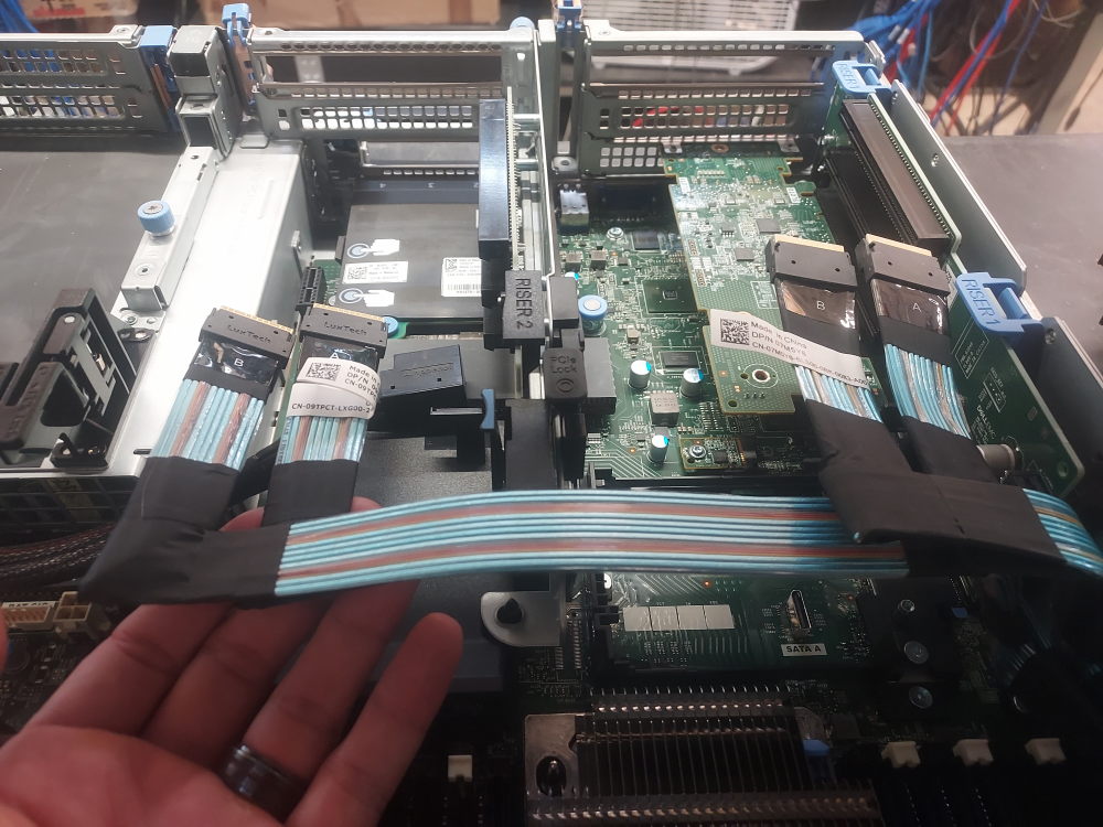
They will connect to the NVME controllers:
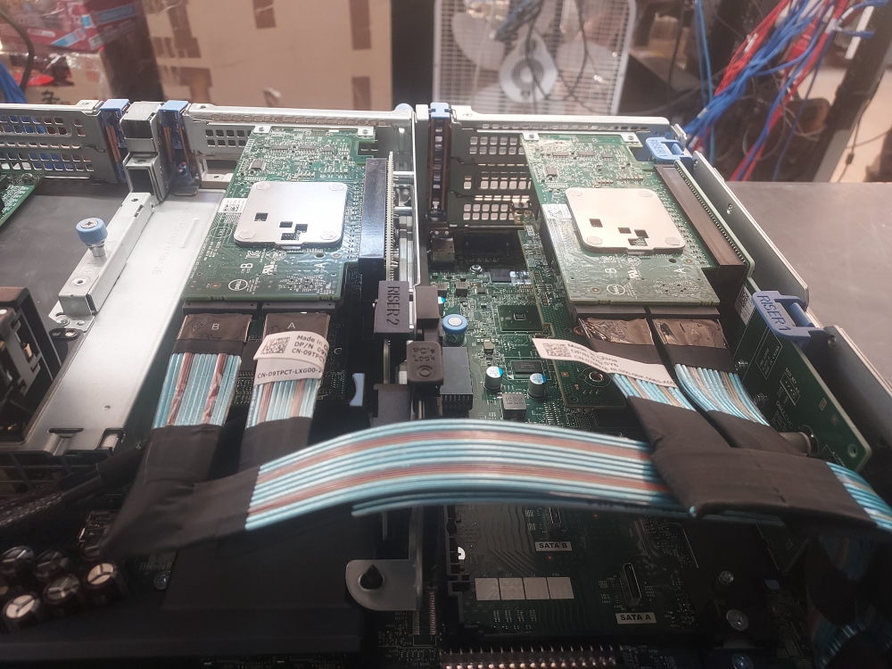
The final NVME cable routes to the left of the chassis to riser 3:
Extra storage configurations
The R740xd can accept extra storage configurations in the rear and inside the chassis. In the rear you have options to install either a x4 SFF or a x2 LFF flex bay. In the chassis you have the option to install a x4 LFF mid bay. All variations of the R740xd support such configurations.
Click here for rear flex bay installation instructions
There are a few prerequisites before you attempt to purchase/install a rear flex bay.
The first consideration is your specific chassis. The 12 Bay LFF and 24 Bay SFF chassis use the same flex bays but use different cables to attach them to the backplane. A cable designed for the 12 bay will not work with the 24 bay.
The second consideration is regarding risers 2 and 3. Both of them must be removed in order to install the flex bay. You’re essentially trading PCIe slots for more storage space with such configuration. You can however install riser 2B or 2C. These are low profile risers that can sit under the flex bay while still providing a single x8 or x16 PCIe slot.
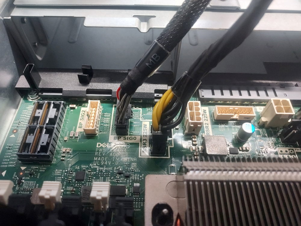
The required power cable and signal cable will be the same regardless of chassis variation.
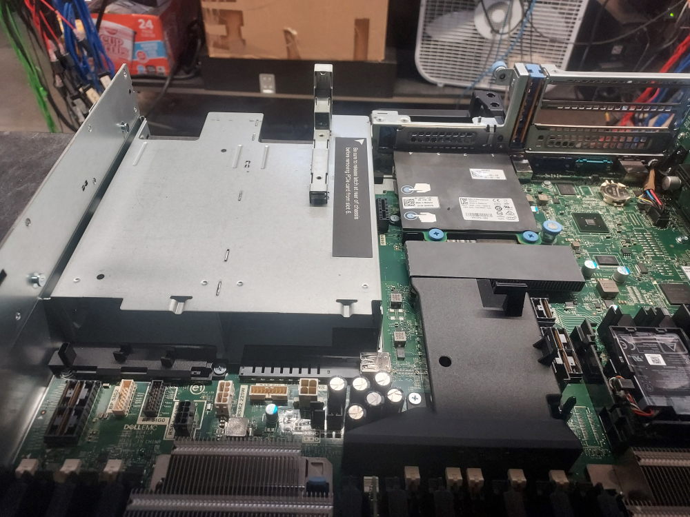
Installing is quite simple. Remove risers 2 and 3 first. What you’re left with is a gaping hole in the rear of the chassis:
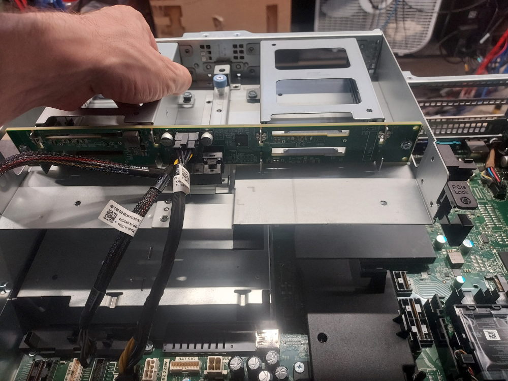
Align the flex bay and slot it into position:
Connect the power and signal cables to the motherboard:
Route the SAS storage cable from the flex bay to the primary backplane:
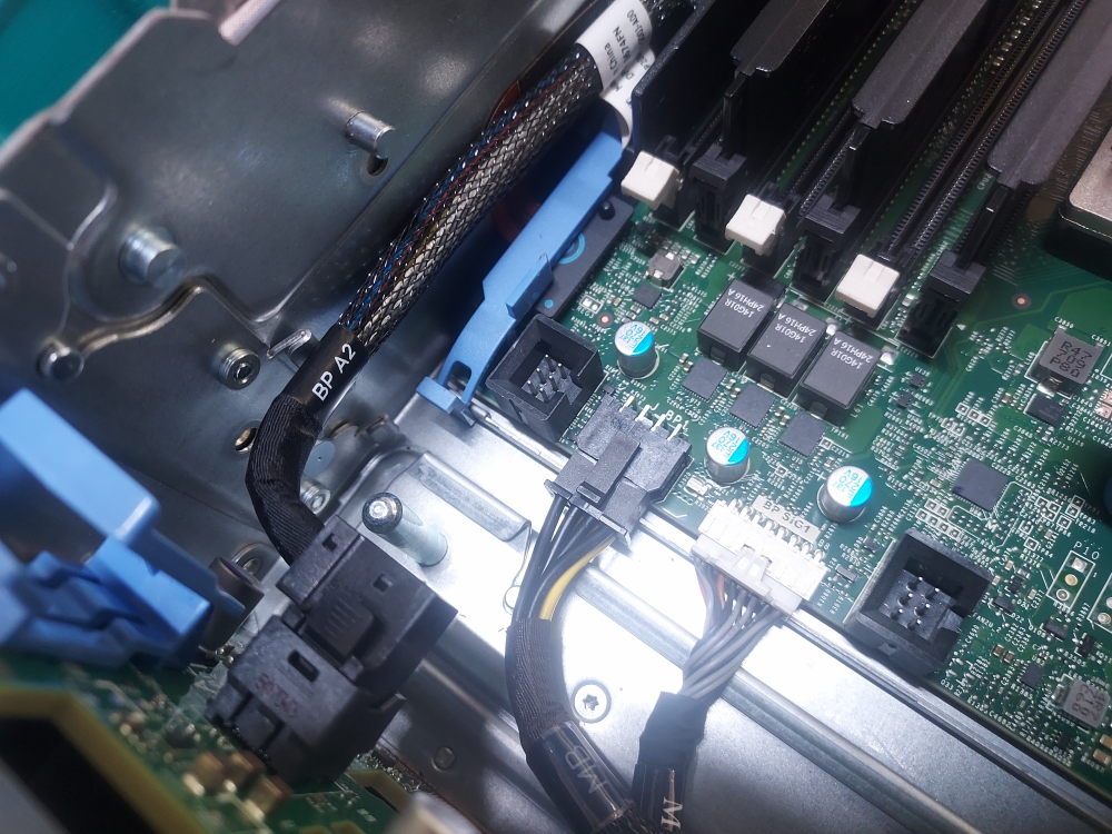
Click for mid bay installation instructions
The R740xd also supports a x4 LFF mid bay. The setup is similar to the rear flex bay. There are 3 primary cables you’ll need to complete the installation. The first cable is the SAS storage cable which connects the mid bay to the primary backplane.
The exact cable you’ll need depends on your backplane:
- This is the cable you need for the R740xd 12 Bay LFF backplane
- This is the cable you need for the R740xd 24 Bay SFF backplane
The other 2 cables are the following signal cable as well as the power cable. These will attach directly from the mid bay to the motherboard.
You will also require the low profile heatsinks. The mid bay will not fit with the high performance 2U heatsinks installed.
Installing can be a bit of a pain but be patient.
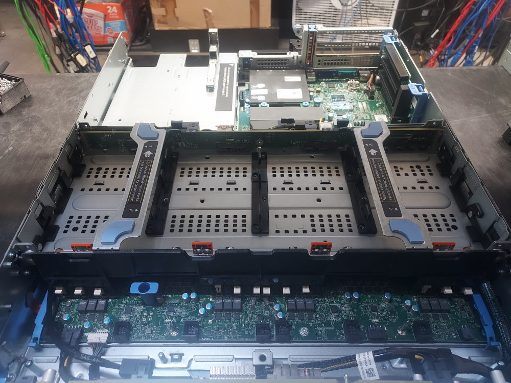
It is helpful to flip the mid bay upside down like this:
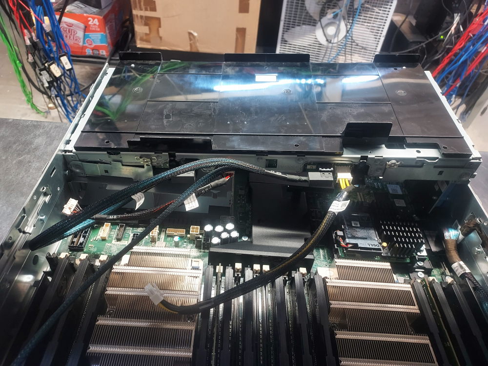
In this position you can plug in the signal cable, the power cable, and route the SAS cable to the backplane. The chassis has a specific channel that allows you to properly route the SAS cable on the side. Stuff the cable in the channel as best you can. The mid bay will not be able to slot into place if the cable is in the way.
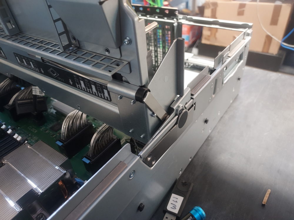
Once the cables are plugged in flip the mid bay over and align the notches on the mid bay with the slots on the chassis. Make note of the alignment arrows:
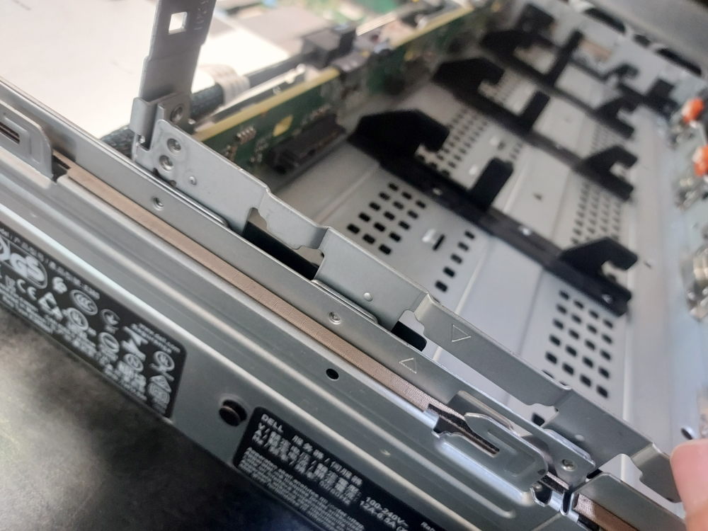
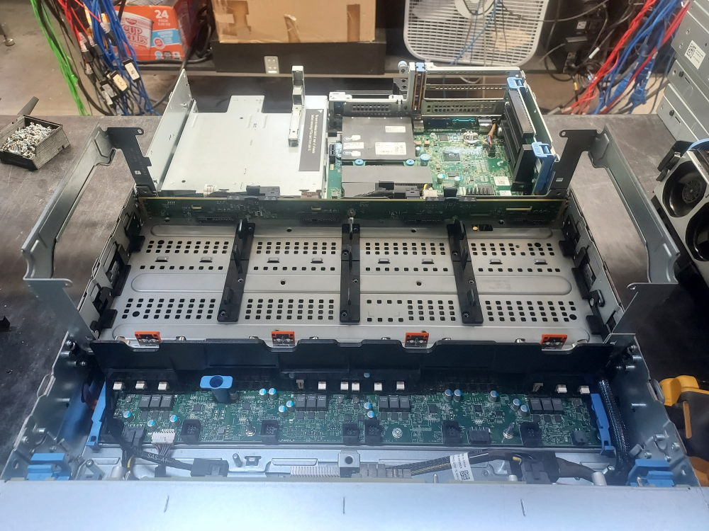
Any drives you put in will require caddies. The drives are first installed into the caddies and then the caddies install into the mid bay.
Lower the handles into their flat position when done:
Installing the Power Supplies
The final major component to install is the power supply. The R740xd has two hot-swappable power supply bays located at the rear of the chassis.
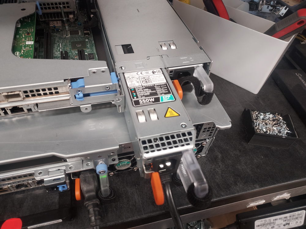
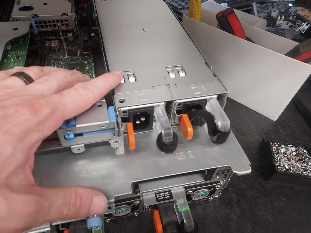
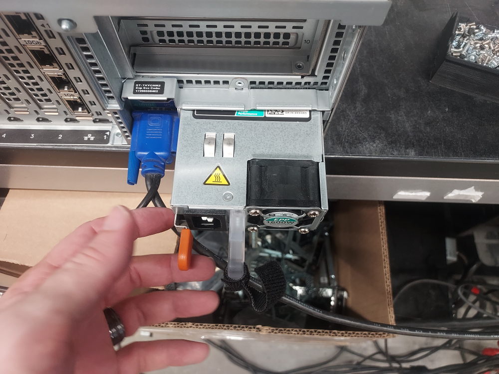
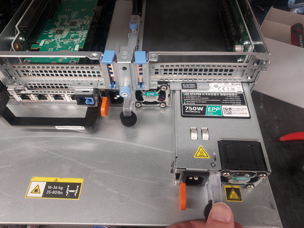
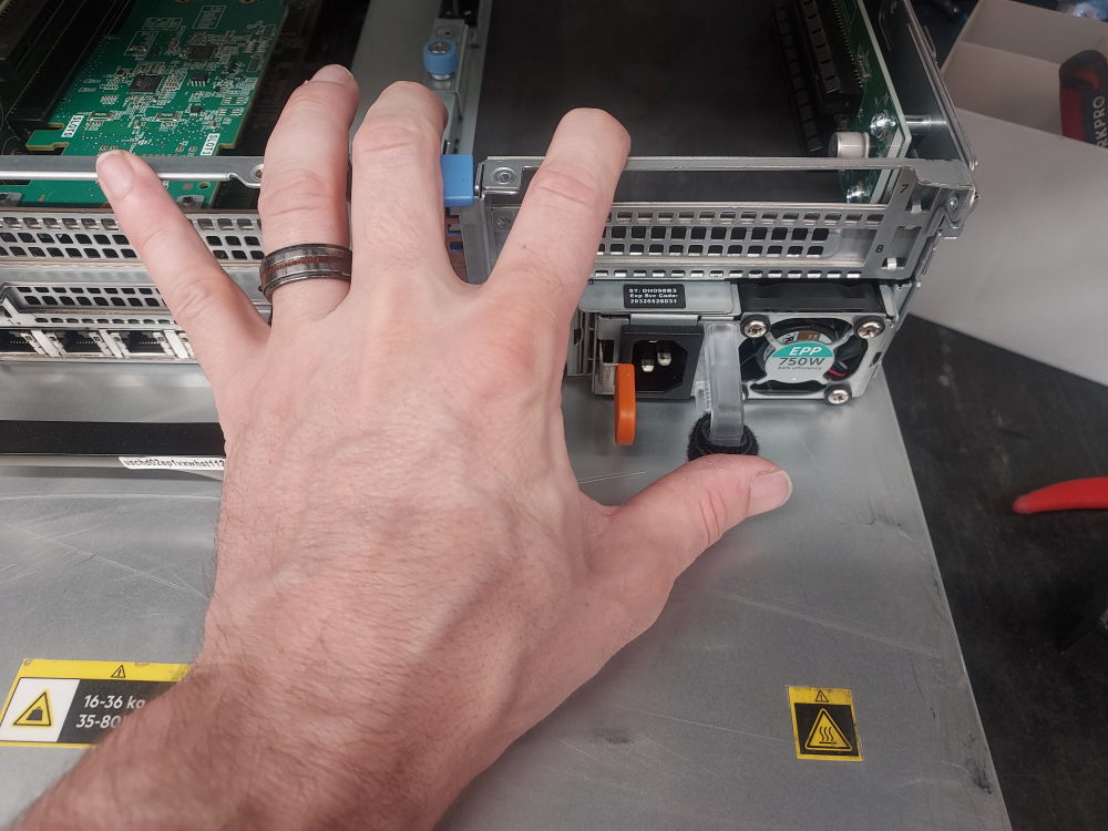
Power supplies slide directly into the rear of the chassis. You can install them from the rear of the server or reach over the chassis from the top if the server is already positioned on a workbench.
Align the power supply with its bay and slide it firmly into place. Apply slightly more pressure as the PSU reaches the end of the bay to ensure that its connector fully engages with the server’s internal power distribution system.
For normal redundant operation, install two compatible power supplies. The two PSUs should be matched appropriately for the server configuration. The required wattage depends on the processors, storage devices, PCIe expansion cards, and other hardware installed in the R740xd.
When building an R740xd from an empty chassis, verify the PSU wattage and efficiency rating before installation rather than assuming that any R740xd power supply will be suitable for every configuration.
Further reading:
R740xd compatible power supplies
R740xd compatible storage drives
R740xd compatible network daughter cards
R740xd compatible memory DIMMs