I came across what appears to be a rebranded Supermicro server. This is a NUTANIX NXS2U1NL06G610. Unfortunately despite many attempts and various user/pass combos I was unable to get into the BMC. This post will explain how to manually set the BMC password using Ubuntu and IPMITOOL. This is not something you can do in the BIOS like Dell or HP.
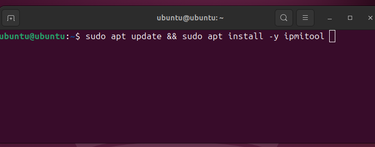
For starters get a copy of Ubuntu and make a bootable USB drive.
Once booted you can open a terminal and install IPMITOOL. The following command will update the package repositories and install the utility automatically:
My recommendation is to perform a complete factory reset of the BMC. This will ensure a clean slate. It’s possible you have a server with a non-default password. You can reset and try the defaults once more. This did not work for me but maybe it will for you.
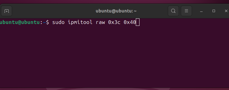
There won’t be any output for this command but you will hear the fans spin up, indicating that the server is resetting.
Once reset you can attempt the default credentials again, otherwise proceed to set a manual password of your own.
List the user accounts on the system with the following command. You should see a user called ADMIN:
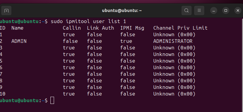
The most important column is the ID field. In my case the ADMIN account corresponds to ID field 2.
Now we can set a password of our own:
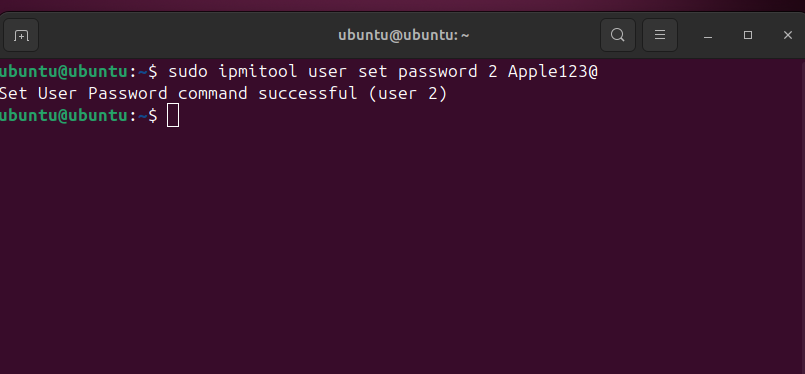
Here we instruct ipmitool to set a new password by giving it the ID of the admin user, in our case 2, and then setting the new password.
This command will tell you if it was successful or not. Sometimes there’s rules on the length and complexity of the password you can use. If you get errors just try other passwords until it lets you through.
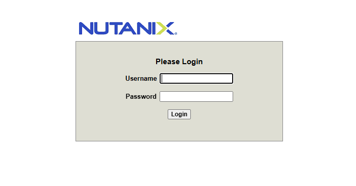
Now you can login in to the BMC interface without problems.