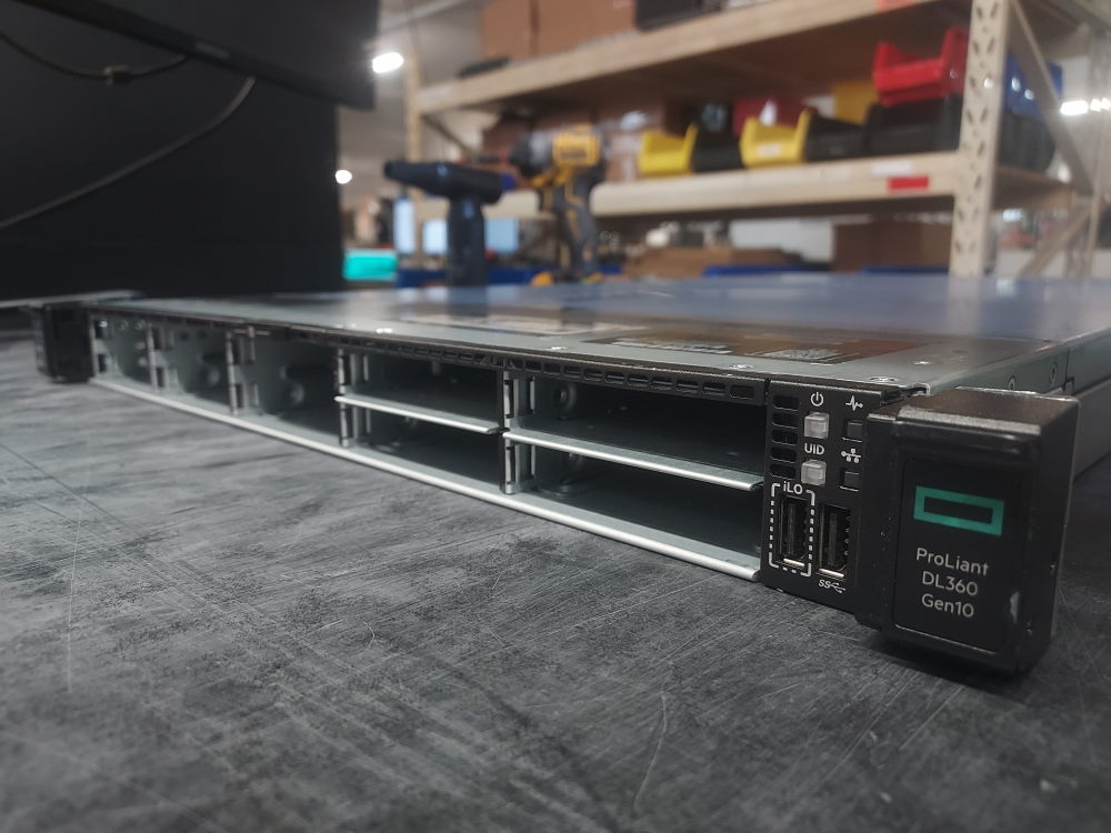
The HPE ProLiant DL360 Gen10 Premium 10-Bay SFF is a unique configuration equipped with an NVMe backplane that provides NVMe support across all 10 front drive bays. With the installation of a Smart Array controller, the first 8 drive bays become “universal,” supporting SAS, SATA, or NVMe drives, while bays 9 and 10 remain NVMe-only.
In this guide, we’ll go through a complete build of this server, covering everything from installing the processors and memory to the RAID controller, Smart Array battery, network daughter card, risers, PCIe cards, storage and NVMe cabling, and power supplies.
Essential Components
Before you begin assembling an HPE ProLiant DL360 Gen10 10-Bay SFF Premium server from an empty chassis, it is important to identify the hardware required to turn the chassis into a functioning server. This configuration is different from the standard 8-bay DL360 Gen10 because it uses a 10-SFF premium backplane and dedicated NVMe hardware to provide a combination of SAS, SATA, and NVMe storage support.
The goal of this section is to identify the major components that should be installed and verified before moving on to the rest of the build. Starting with the bare chassis, you will need to install and configure the motherboard, processors, memory, storage backplane and cabling, cooling system, Smart Array controller, network daughter card, PCIe risers, expansion cards, and power supplies.
Motherboard
The motherboard should already be installed in the chassis and securely fastened in place. It serves as the central connection point for the server’s processors, memory, storage, expansion cards, networking hardware, cooling system, and power delivery.
The processors and memory modules are installed directly onto the system board. PCIe risers connect to the motherboard and provide expansion slots for network adapters, storage controllers, and other PCIe devices. The front storage backplane connects to the appropriate storage controller and NVMe hardware through dedicated cabling.
The DL360 Gen10 also uses a network daughter card, which installs directly into the system board and provides the server’s integrated network interfaces. The hot-plug fan modules connect to the motherboard through dedicated fan connectors.
Before installing the remaining components, make sure the motherboard is properly seated and secured inside the chassis. A loose or incorrectly installed system board can prevent the server from powering on or cause individual components to malfunction.
Backplane and Cables
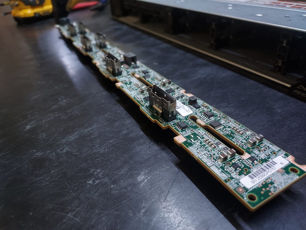
The 10-SFF premium backplane is one of the most important components in this particular DL360 Gen10 configuration. HPE identifies the 10-SFF NVMe/SAS/SATA backplane as spare part 875556-001.
This backplane provides the physical connections for all ten front drive bays. Unlike a standard 8-SFF SAS/SATA configuration, the premium configuration is designed to provide both traditional SAS/SATA storage and direct NVMe connectivity.
The ten drive bays are divided into two functional groups. Bays 1 through 8 can support a mixture of NVMe and SAS drives, while bays 9 and 10 are NVMe-only when the 10-SFF NVMe/SAS backplane option is installed.
This makes the first eight bays effectively universal from a drive-type perspective, provided the appropriate storage controller and NVMe connections are installed. The final two bays are dedicated to NVMe storage.
The backplane requires several different cable connections depending on the storage configuration. HPE’s cabling documentation identifies separate connections between the backplane, the Smart Array controller, and the NVMe riser. For the 10-SFF configuration, HPE lists dedicated cables for the NVMe connections (see below) as well as a separate SAS cable for the connection to the Smart Array controller.
For the premium configuration, particular attention should be paid to the individual cable types and their port assignments. The cables can look similar, but each cable is designed for a specific connection between the backplane, controller, or NVMe riser.
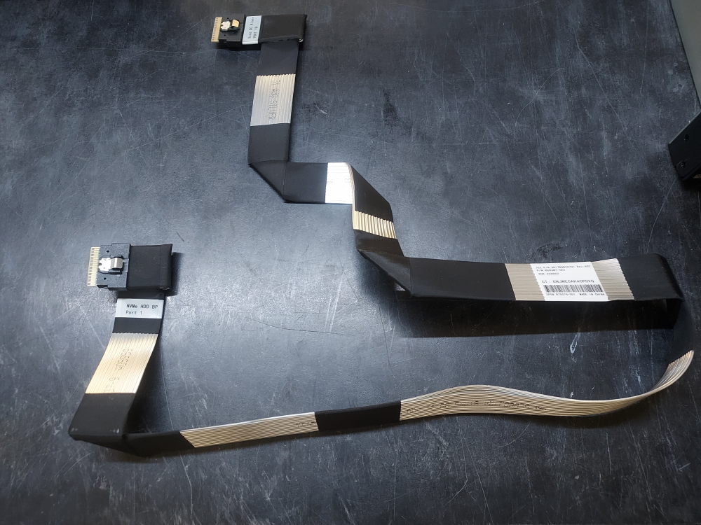
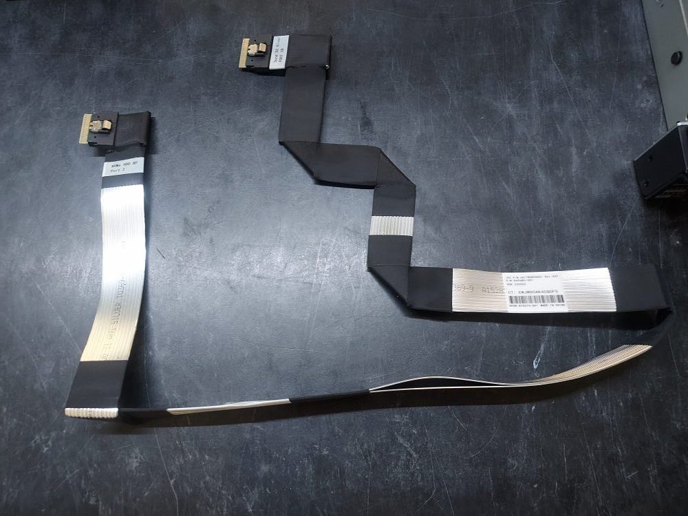
There are 3 different cables you’ll need to connect the NVME backplane to the NVME riser.
Click to see picture of NVME cable for Port 1
Click to see picture of NVME cable for Port 2
Click to see picture of NVME cable for ports 3, 4, and 5
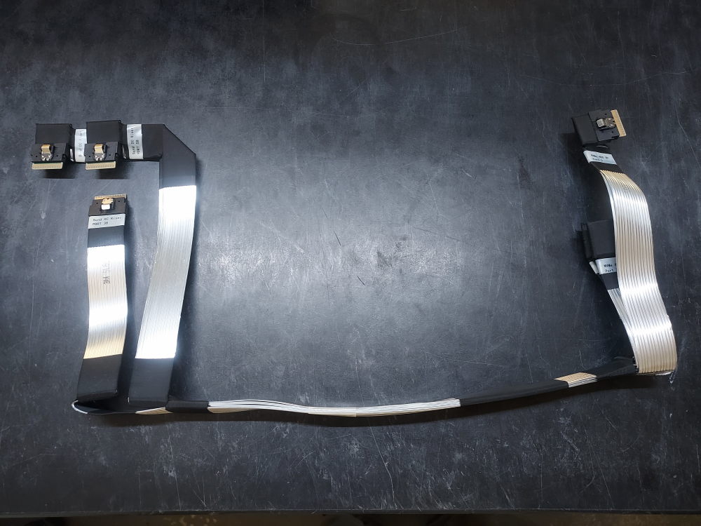
The Smart Array controller provides the SAS/SATA storage connection, while the NVMe drives use dedicated PCIe connectivity. HPE’s DL360 Gen10 cabling documentation specifically includes configurations for a 10-SFF NVMe backplane connected to an NVMe riser and for the 10-SFF premium backplane connected to the P824i-p Smart Array controller.
Before proceeding with the rest of the build, inspect the backplane and confirm that the required backplane power cable, SAS, and NVMe connections are present. Verify each cable against its intended port before installation.
Correct cabling is particularly important on this configuration. A drive can be physically installed in a bay but still remain unavailable to the operating system if the corresponding storage controller or NVMe PCIe connection has not been properly connected.
For a complete 10-bay configuration, the storage system should therefore be treated as two interconnected subsystems:
- SAS/SATA storage — connected through the Smart Array controller.
- NVMe storage — connected through the dedicated NVMe PCIe/riser connections.
The exact cable arrangement depends on the controller and NVMe configuration being built, so the individual cable part numbers and port assignments should be verified before installation.
Cooling
The DL360 Gen10 uses a combination of hot-plug fan modules, processor heatsinks, and an air baffle to maintain proper operating temperatures throughout the 1U chassis.
The fan modules are individually installed into the chassis and connect to the system board through dedicated fan connections. HPE identifies the DL360 Gen10 fan modules as hot-plug components, allowing individual fan modules to be replaced without removing the entire server from service.
The processor heatsink mounts directly above each Intel Xeon Scalable processor and transfers heat away from the CPU into the airflow generated by the fan modules. The air baffle directs airflow through the processor, memory, and other internal components.
The DL360 Gen10 has different cooling configurations depending on the installed processors and hardware. For higher-power processors and configurations with increased thermal requirements, HPE offers the DL360 Gen10 High Performance Heat Sink Kit (873591-001) and High Performance Fan Kit (871244-B21).
For a 10-bay NVMe configuration, cooling should be treated as an important part of the overall build rather than an optional finishing component. NVMe drives, high-power processors, storage controllers, and PCIe expansion cards can all contribute to the thermal load inside the 1U chassis.
Before powering on the completed server, make sure the appropriate fan modules, processor heatsinks, and air baffle are installed and that all required fan connections are properly seated.
Risers
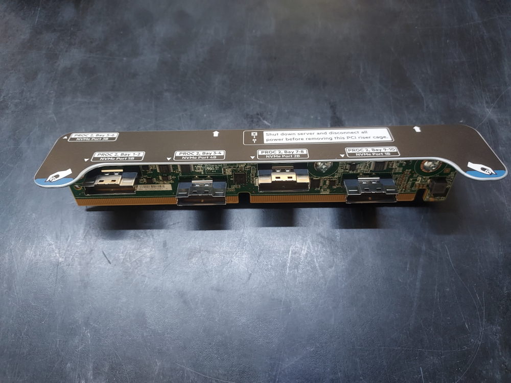
The DL360 Gen10 uses several different PCIe riser configurations depending on the intended hardware. The risers provide expansion slots for Smart Array controllers, network adapters, NVMe hardware, GPUs, and other PCIe devices.
The 10-SFF NVMe configuration is particularly important because it uses a dedicated NVMe riser to provide the PCIe connectivity required by the front NVMe drives. HPE’s QuickSpecs identifies a 5-port 10-SFF NVMe Riser Kit, which provides connections for up to ten NVMe SSDs. This riser is included with certain 10-SFF chassis configurations and the 10-SFF Premium Backplane Kit.
The DL360 Gen10 also supports other riser configurations, including an x16/x8 primary riser, a low-profile x16 riser, and other PCIe configurations. The correct riser depends on the chassis configuration and the expansion hardware being installed.
When building a 10-bay premium server from an empty chassis, it is therefore important not to assume that any DL360 Gen10 riser will work with the configuration. The NVMe riser and its associated cabling are specifically required for the front NVMe storage connections.
The riser board installs into its corresponding riser cage and connects to dedicated PCIe connectors on the system board. Before installing an expansion card, verify that the riser provides the required PCIe slot type, lane width, physical height, and electrical connectivity.
For this particular build, the riser configuration should be established before installing the Smart Array controller, NVMe cabling, and other PCIe expansion cards. This helps ensure that each card is installed in the correct position and that there is sufficient room for the required cabling.
Building the server
Assuming you have all the required components listed above we can begin adding components.
Before starting, also ensure you have the following tools:
- T30 bit
- T20 bit
- T10 bit
- Phillips #2 bit
- Compressed air
- Thermal paste
Installing the processors
Open the lid to expose the inner components and remove the heatsinks or CPU covers. It is first necessary to inspect the pins prior to installing the other components. If for whatever reason the CPU pins are damaged you should highly consider not continuing the build, especially if the server will be going into any serious production environment.
Remove the heatsink to expose the CPU socket. Blow out any dust or debris with the compressed air:
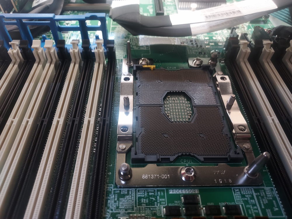
Place CPU in the socket. If you prefer you can install the processor on the heatsink and then just install the heatsink. I have found sometimes the CPU can slip out of the black plastic bracket and damage the CPU pins, so I like to install the CPU into the socket first, and then install the heatsink next. Be sure to orient the arrow on the CPU with the arrow on the motherboard.
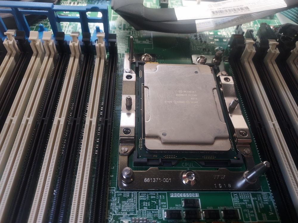
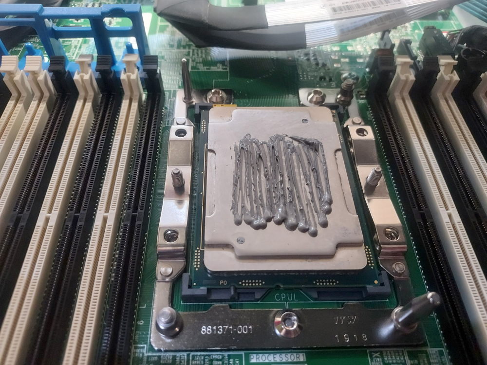
Apply thermal paste:
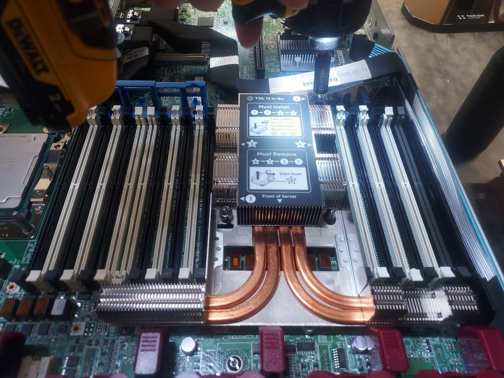
Install the heatsink. You will need the T30 bit for this:
Installing the memory
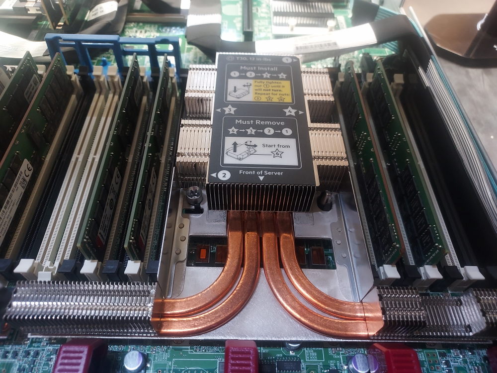
For this build I have 8 DIMMs in total. I’ll assign 4 to CPU1 and 4 to CPU2. In general you want to populate the white DIMMs first before populating the black dimms. Because I have 4 DIMMs per CPU I will populate DIMM slots 3, 5, 8, and 10. If you have a different amount consult the memory population guidelines below.
Click here for memory population guidelines
| Number of DIMM(s) to populate per cpu |
DL 360 G10 memory population guidelines | |||||||||||
|---|---|---|---|---|---|---|---|---|---|---|---|---|
| Ch 6 | Ch 5 | Ch 4 | Ch 1 | Ch 2 | Ch 3 | |||||||
| 1 | 8 | |||||||||||
| 2 | 8 | 10 | ||||||||||
| 3 | 8 | 10 | 12 | |||||||||
| 4 | 3 | 5 | 8 | 10 | ||||||||
| 5 | 3 | 5 | 8 | 10 | 12 | |||||||
| 6 | 1 | 3 | 5 | 8 | 10 | 12 | ||||||
| 7 | 1 | 3 | 5 | 7 | 8 | 10 | 12 | |||||
| 8 | 3 | 4 | 5 | 6 | 7 | 8 | 9 | 10 | ||||
| 9 | 1 | 3 | 5 | 7 | 8 | 9 | 10 | 11 | 12 | |||
| 10 | 1 | 3 | 4 | 5 | 6 | 7 | 8 | 9 | 10 | 12 | ||
| 11 | 1 | 3 | 4 | 5 | 6 | 7 | 8 | 9 | 10 | 11 | 12 | |
| 12 | 1 | 2 | 3 | 4 | 5 | 6 | 7 | 8 | 9 | 10 | 11 | 12 |
Installing the smart array battery
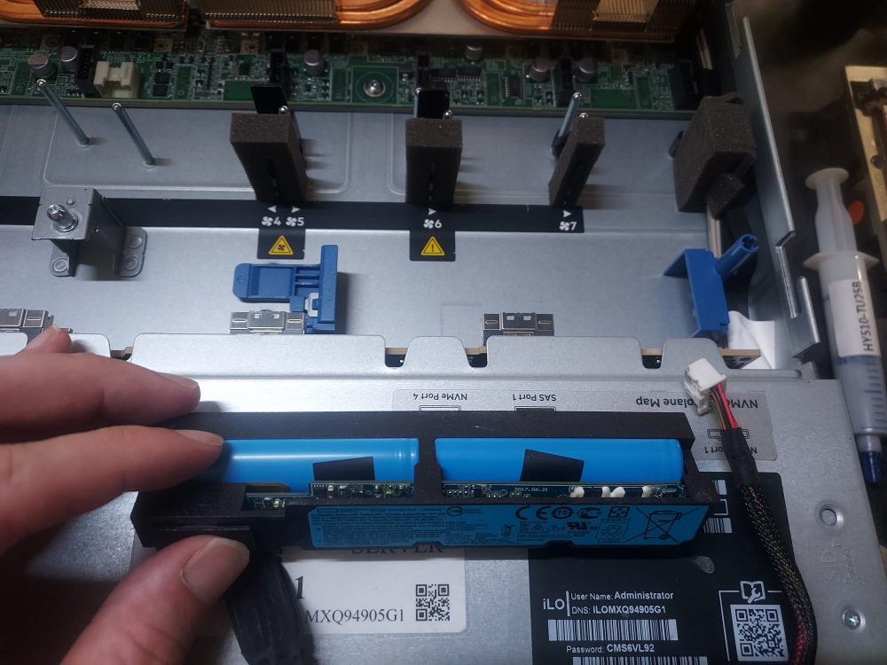
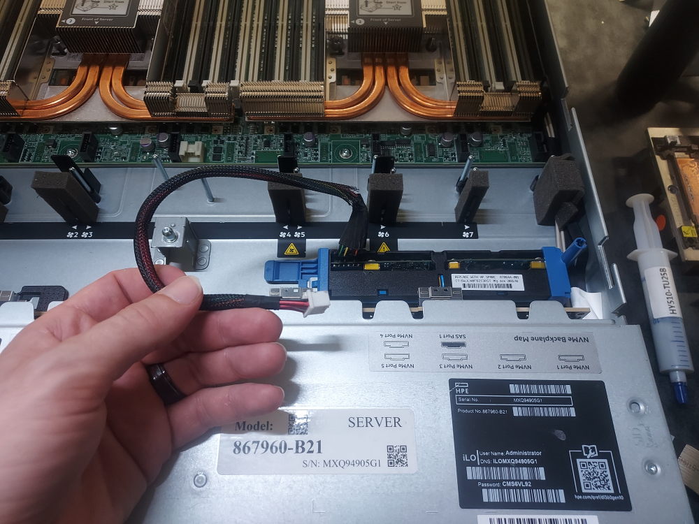
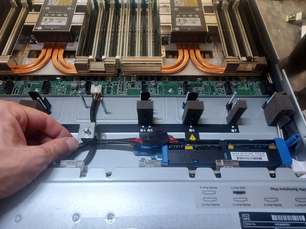
At this point I like to install the smart array battery. This is the battery that maintains the RAID controller cache in the event of a power outage. Start by removing any cables attached to the backplane. If your server already has the full set of NVME and SAS cables installed, these have to be removed in order to install the battery. You will also need to remove the fans (at least the center fan.)
Installing the Smart Array Raid controller
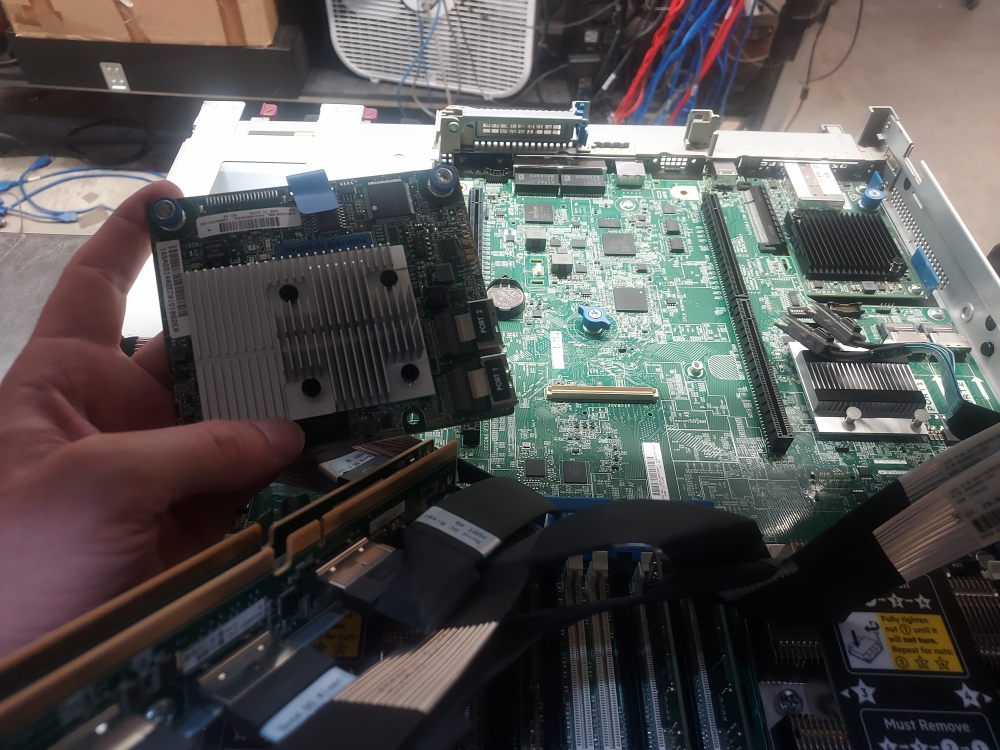
The smart array controller is what will allow the server to recognize SAS and SATA drives. The NVME cables alone will only support NVME drives. In order for the drive bays to be truly universal (supporting SAS, SATA, and NVME) you must have both the smart array controller and NVME cables installed.
It is best to install the Smart Array controller with the cables removed from the system. The controller will sit under the cables and it’s a lot easier to install prior to NVME cable installation. It is also helpful to remove the risers although not completely necessary.
This controller has a proprietary connection to the motherboard as seen here:
There are 2 holes in the controller. Line them up with the blue pegs on the board. Tighten down the screws.
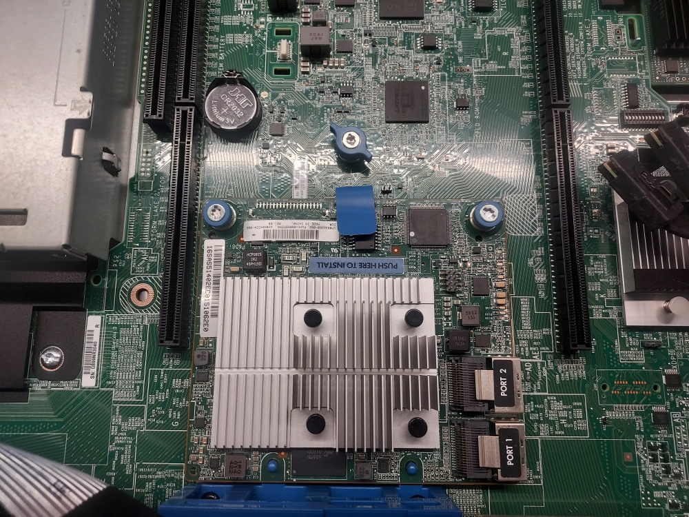
Plug in the Mini SAS cables if you have the cable installed already. We’ll cover installing the cables in the next section.
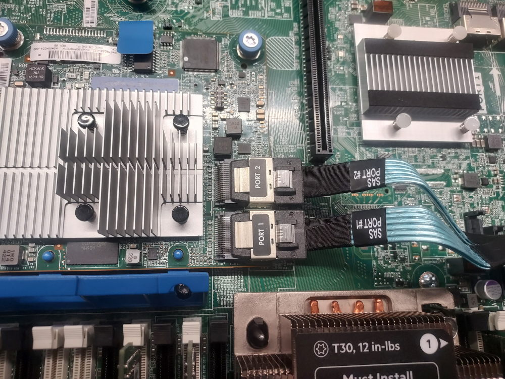
NVME and SAS cabling
Now it’s time to install the cables. The first cable you want to install is the blue Mini SAS cable shown above. This attaches from the backplane and then to the smart array controller.
This is the installation location on the backplane. Route it along the right side of the chassis. It will make a 90 degree left turn before the riser and plug in to the smart array controller.
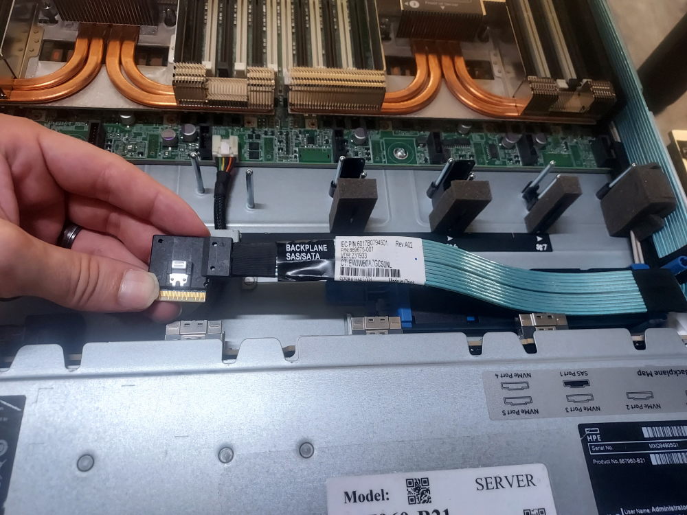
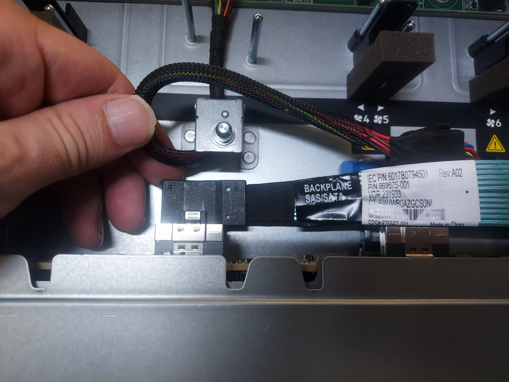
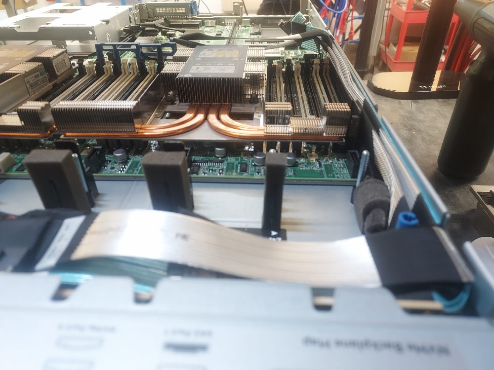
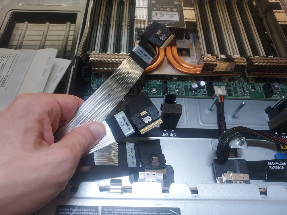
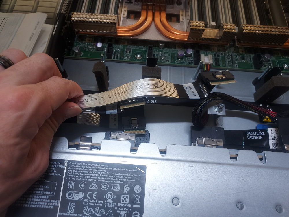
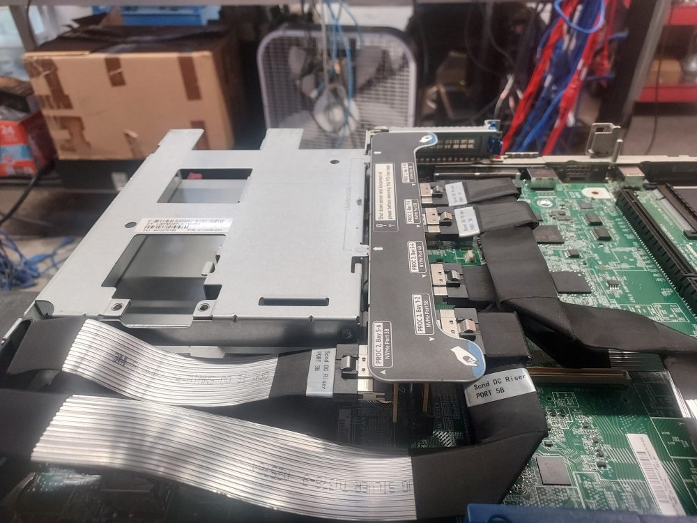
Now that the mini SAS cable is plugged in it’s time to install the NVME cables. These cables will plug into the backplane and route to the rear of the server where they will be plugged into the dedicated NVME riser. Cables that plug in to ports 1 and 2 on the backplane will route to the right side of the server. NVME cables port 3, 4, and 5 will route to the left.
NVME cables port 1 and 2:
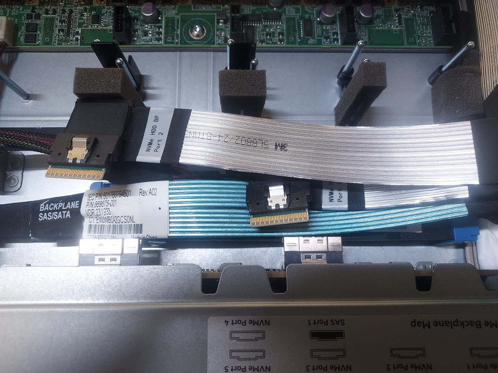
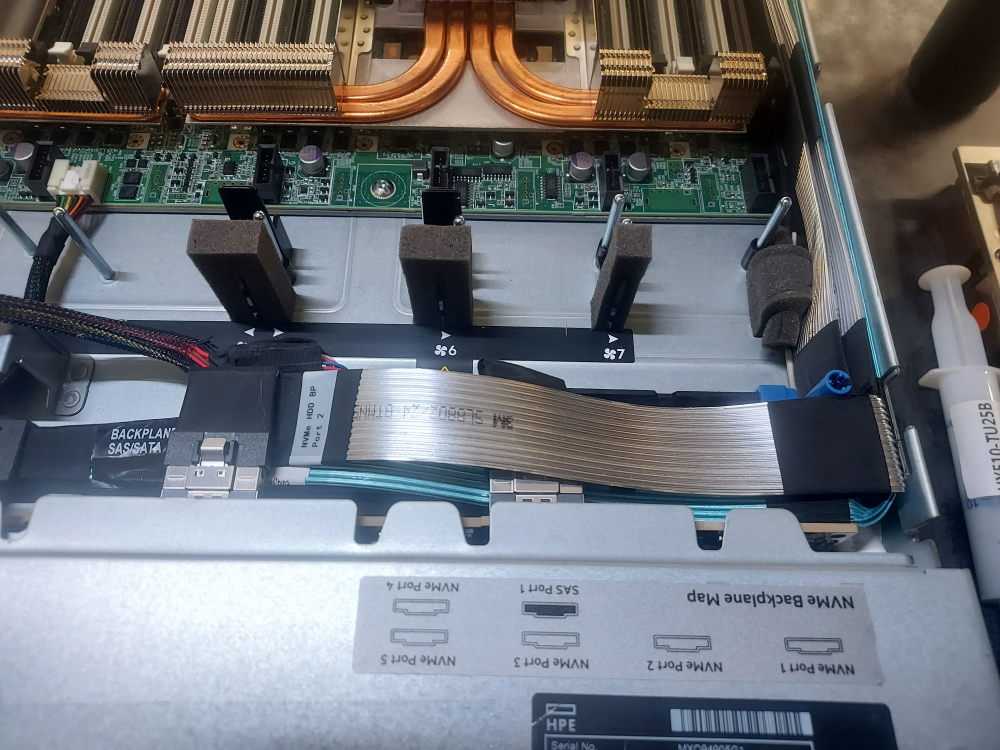
Here you can see how the cables route along the edge of the chassis:
NVME cables port 3, 4, and 5
Now for the last set of cables. These install into their respective ports on the backplane like ports 1 and 2. These cables however will route to the left side of the chassis.
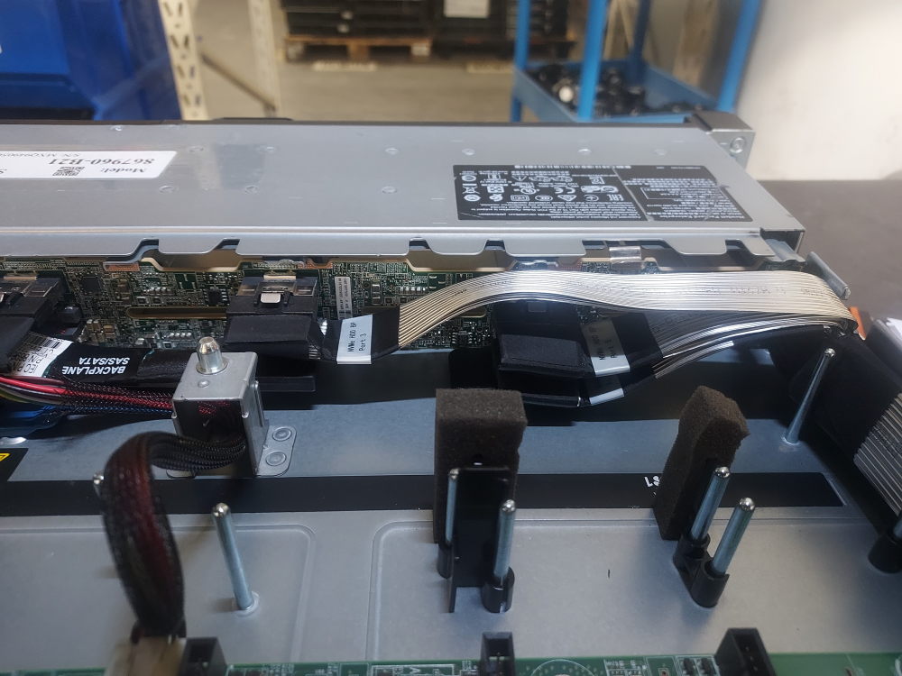
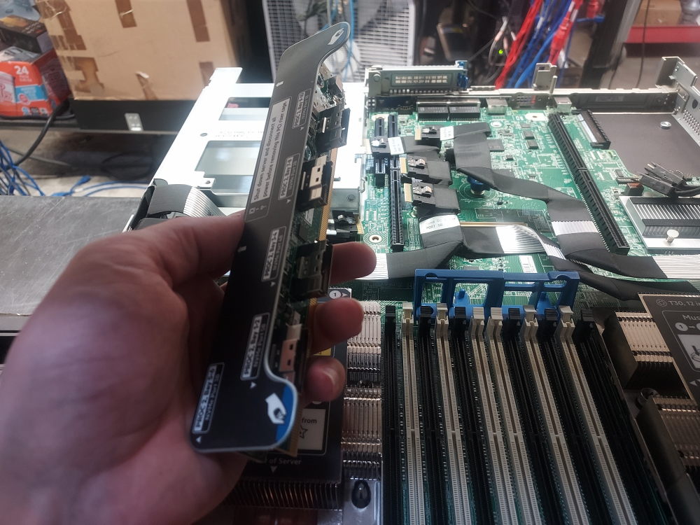
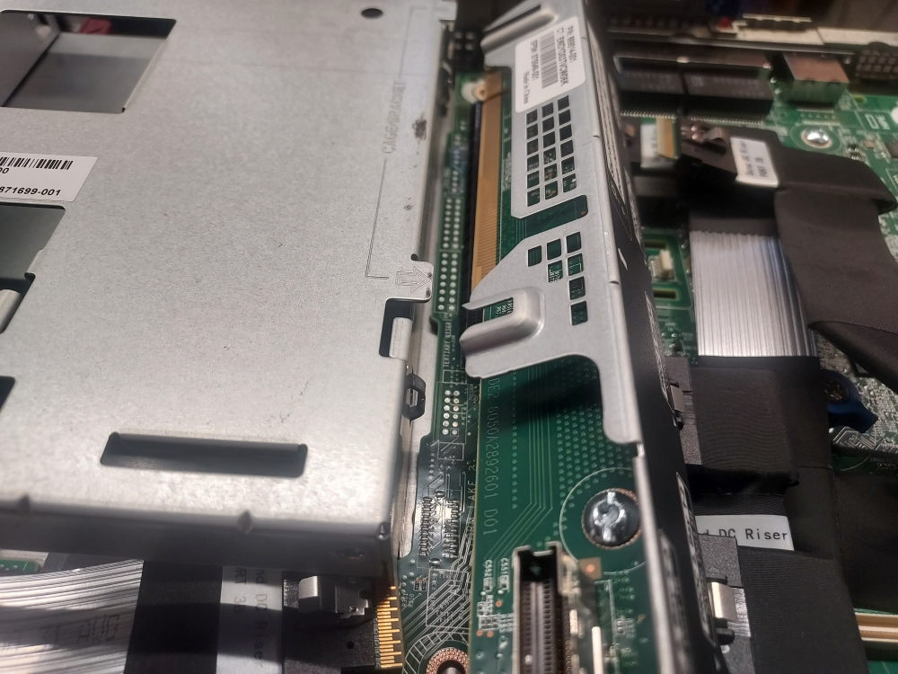
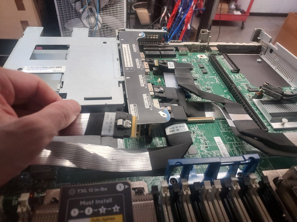
Installing NVME riser and plugging in cables
All of these cables now plug in to the NVME riser.
Installing NDC
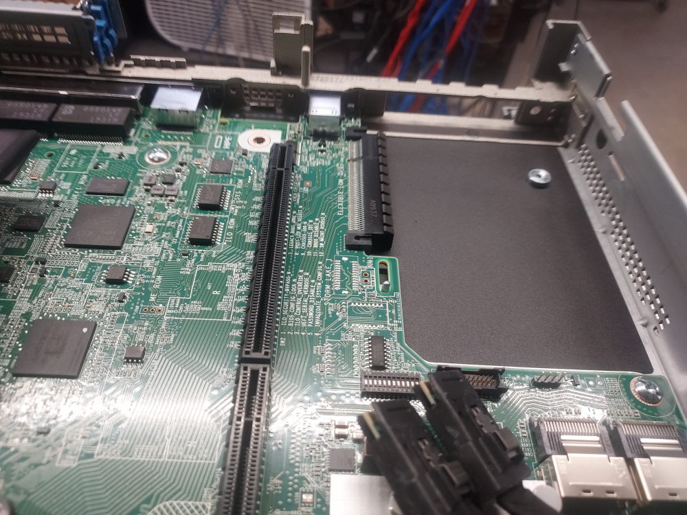
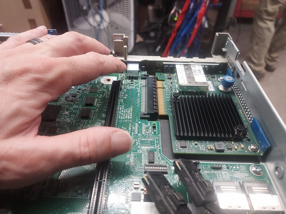
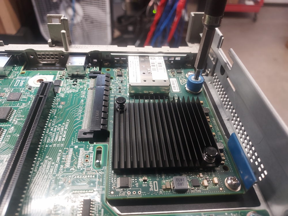
The NDC will install below riser 1. Remove riser 1 and remove any blank slot fillers prior to installation of NDC.
Installing PCIe card
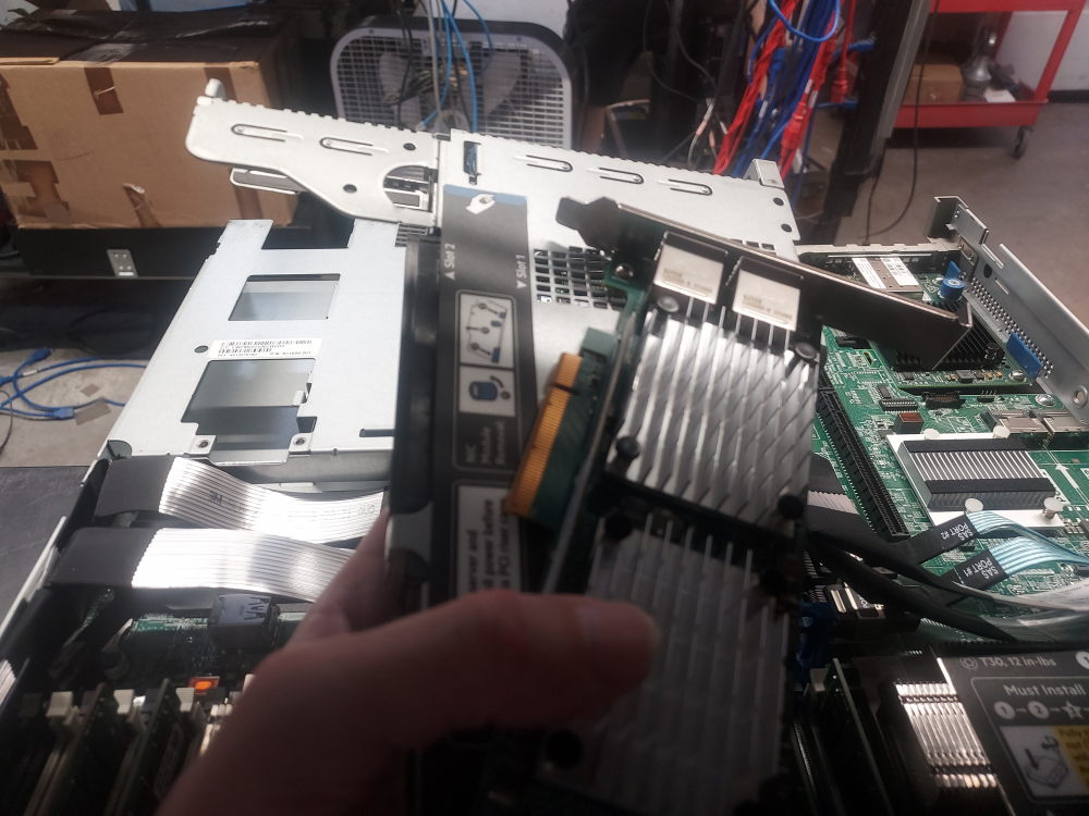
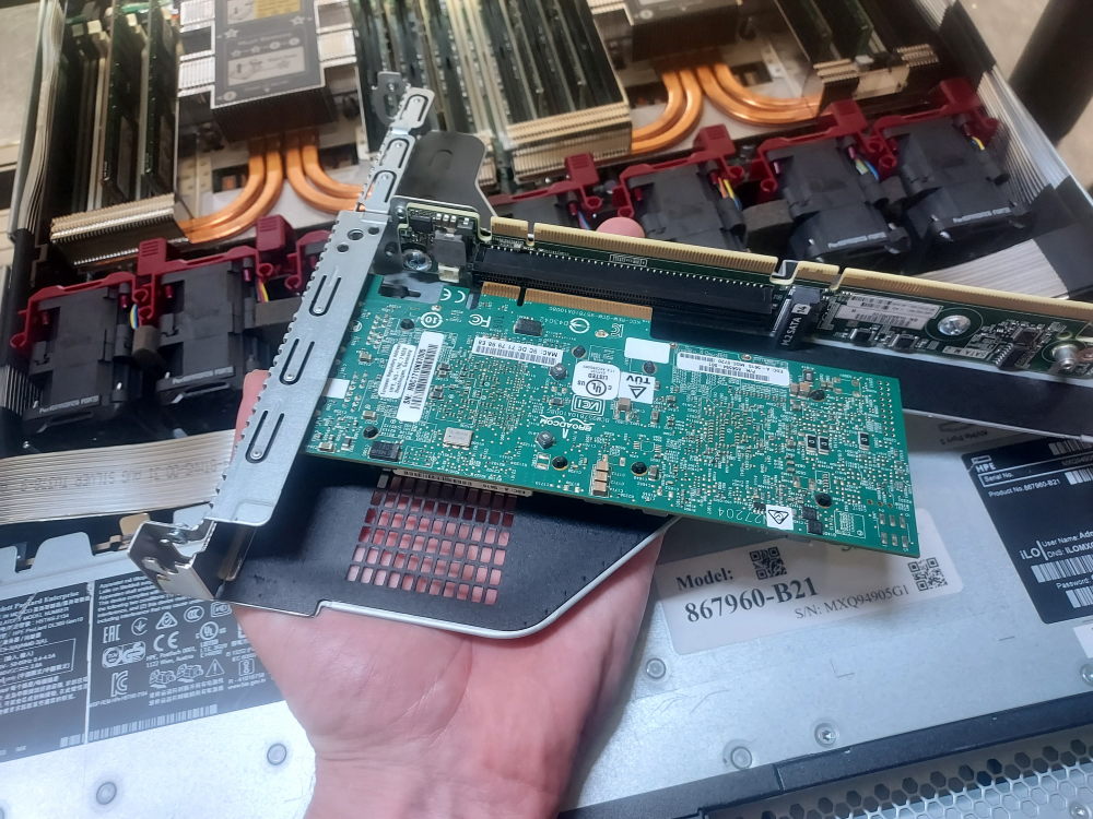
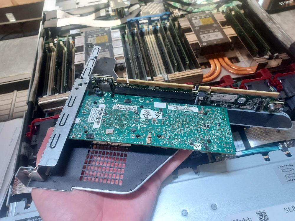
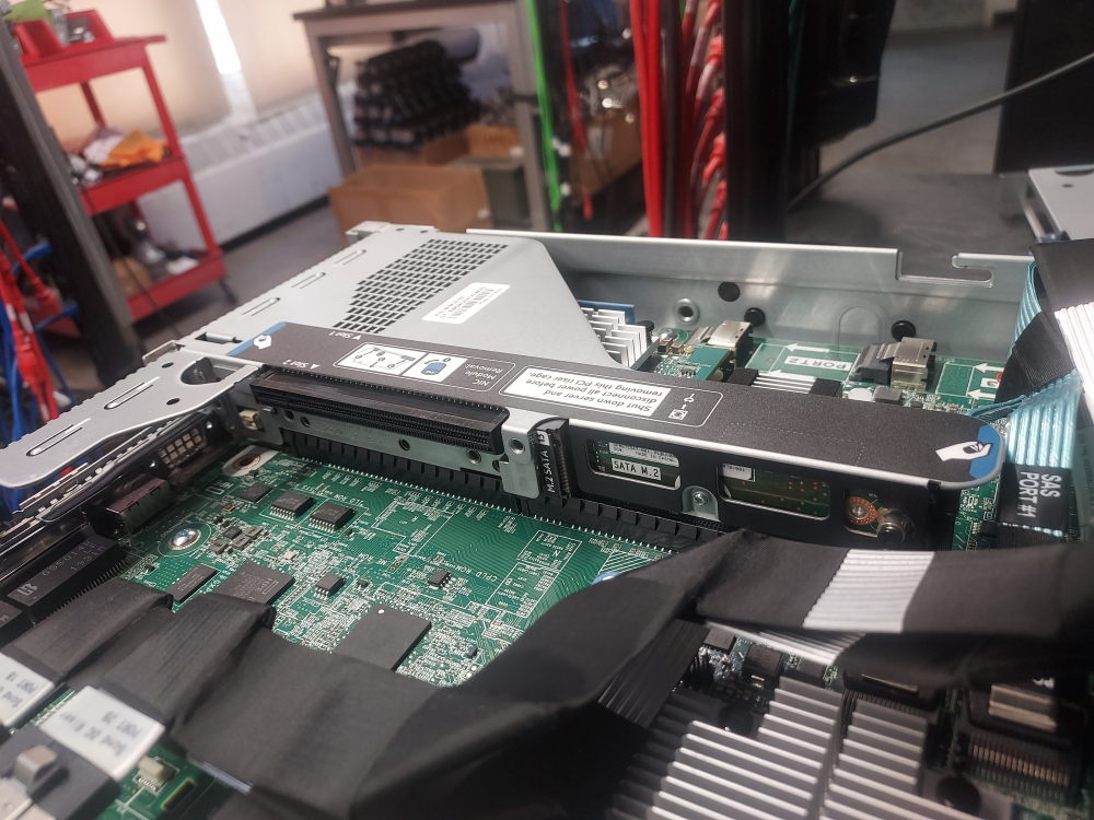
With the riser removed it’s time to install any PCIe cards you have. The primary riser has a full height and half height slot available. Here I will install a card in the full height slot:
Installing power supplies
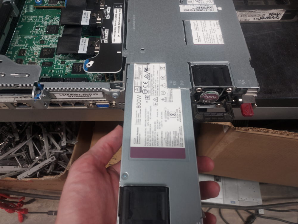
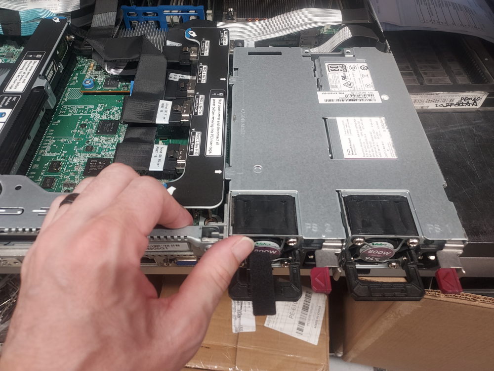
The very last thing to do is install the power supplies.
Cleaning up
Prior to powering on for the first time ensure everything is in its place. If you removed the fans during installation reinstall them. Ensure all cables are properly routed and neatly tucked in to the side channels. If they’re not, it may be difficult getting the lid back on. If you’ve determined that everything is in order, plug in the power supplies and power the server for the first time.
Leave a Reply