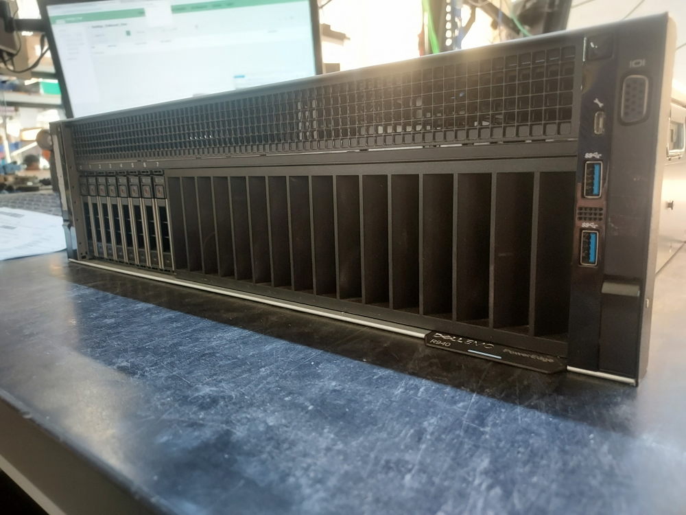
This guide documents the process of building a Dell PowerEdge R940 from an empty chassis. We’ll cover the processors, memory, processor expansion module, storage backplane, cabling, cooling, risers, network adapter, RAID/HBA controller, and power supplies required to turn a bare chassis into a functioning server.
Before you begin assembling an R940, it is important to identify the hardware required to turn the chassis into a functioning server. This section covers the major components that should be installed and verified before moving on to the rest of the build.
The goal is to start with a bare chassis and make sure you have everything necessary to power the system on, recognize the installed hardware, and eventually install an operating system.
Motherboard
The motherboard should already be installed in the chassis and securely fastened in place. It serves as the central connection point for nearly all of the server’s hardware. The R940 processor expansion module or mezzanine will also plug in to the motherboard through a set of 2 or 4 cables depending on the configuration.
The R940 is a four-socket 4U server, so the system board provides connections for up to four Intel Xeon Scalable processors along with their associated memory. 2 of the processors install directly on the motherboard. The other 2 will install onto the expansion module.
Before installing additional components, make sure the motherboard is properly seated and secured inside the chassis. A loose or incorrectly installed system board can prevent the server from powering on or cause other hardware to malfunction.
Processor expansion module
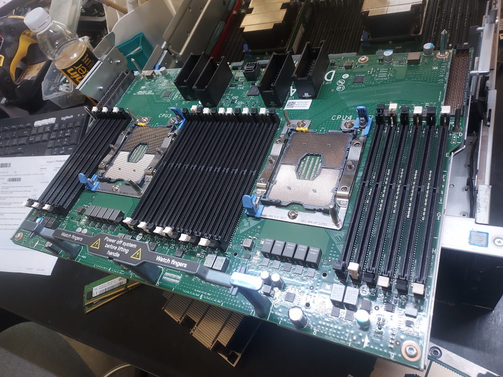
If you will be installing all 4 processors you will need the processor expansion module. This part may also be referred to as the mezzanine. The module will expand the system to support an additional 2 processors. This is a required part if you want to enable your system with the maximum number of CPUs. You can configure the R940 as 2 processor system. This will require a different set of cables then what is required to enable a system with 4 processors.
This expansion module requires 4 of these cables. These are called UPI cables. They connect to the primary motherboard.
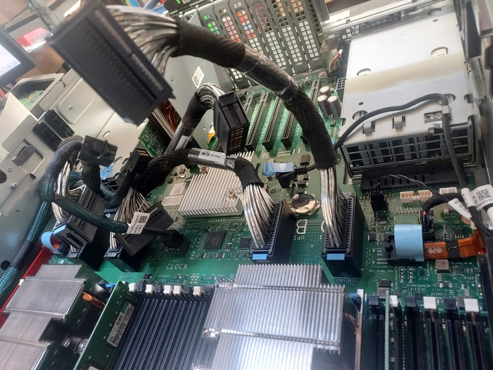
The last cable required by the PEM is the clock cable. This looks like a mini SAS HD cable but it functions more like a signal cable for the multi-CPU architecture of the R940 rather than a storage cable.
Backplane and Cables
The storage backplane is another critical component of the R940. It provides the connections that allow the front-mounted drives to communicate with the server’s storage controller while also supplying power to the drive bays.
Dell manufactured multiple variations of this server. This is the backplane for the 8 bay SFF model.
The backplane will have 2 cables that connect it to the motherboard. One of these cables is a signal cable. The other is a power cable.
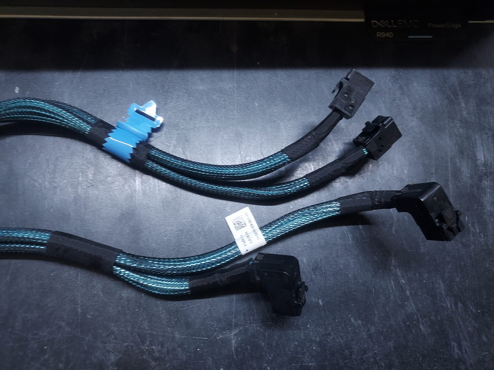
If you’re installing a RAID or HBA controller you will also require the following cable. This is the PCIe SAS storage cable that connects the backplane to the storage controller. It is specific to the 8 Bay SFF backplane.
Before proceeding with the build, inspect the backplane and confirm that all required signal, power, and storage-controller connections are present and properly seated. These connections are essential for the server to detect and communicate with the installed drives.
Cooling
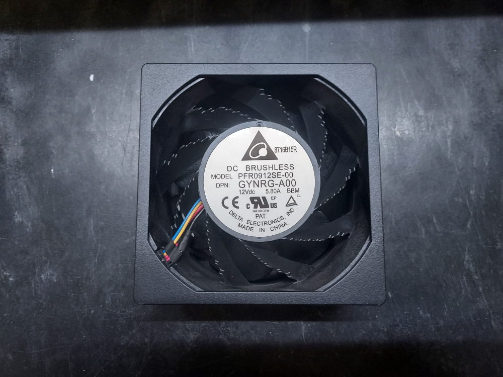
The R940 uses a combination of hot-swappable fan modules, processor heatsinks, and an air shroud to maintain proper operating temperatures throughout the system. These components work together to move air through the 4U chassis and remove heat from the processors, memory, storage components, and PCIe hardware. The fans install into the following assembly cage.
The fan modules are a particularly important part of the R940’s cooling system because the server can contain up to four processors and a large number of expansion and storage components. The correct fan configuration therefore depends on the hardware installed in the system.
Unlike a smaller 1U or 2U PowerEdge server, the R940’s cooling requirements need to be considered alongside the processor configuration, memory population, PCIe cards, storage configuration, and other installed hardware.
The processors also require compatible heatsinks. Because the R940 supports up to four processors, a fully populated four-CPU configuration requires four processor heatsinks.
The appropriate heatsink should be matched to the processor and system configuration. Each heatsink must be properly secured to maintain adequate contact with the processor and allow heat to be transferred into the chassis airflow.
The final major component of the R940’s cooling system is the air shroud. Positioned over the motherboard, the shroud helps channel airflow from the fan modules through the areas containing the processors, memory, and other heat-producing components.
Operating the server without the appropriate air shroud can disrupt the intended airflow pattern and reduce cooling performance.
The fans, processor heatsinks, and air shroud all work together as part of the R940’s thermal management system. Before powering on a server assembled from an empty chassis, verify that the appropriate fan modules and heatsinks are installed and that the air shroud is securely in place.
Risers
The R940 has a substantially more extensive PCIe expansion system than the R740 because of its larger 4U chassis and four-processor design. This means many of your PCIe devices will plug in directly to the motherboard rather than the risers. If you have the processor expansion module installed the system does support up to 2 risers assuming you’re running a 4 CPU configuration.
There is a left riser and a right riser. These plug into the processor expansion module and add an additional 6 PCIe x16 slots to the system. These risers are connected to CPU3 and CPU4 so please ensure you have those processors installed onto the expansion module.
Please note the riser links above are technically part numbers for the PCB. Also required are the left riser assembly cage and right assembly cage. The PCB attaches to these metal cages. These usually come together as a pair on the second hand market but the distinction is worth noting.
Building the server
Once you have all the required components you can begin assembling the server. Aside from the server components there are a number of tools you will need to complete the assembly.
Required tools:
- Torque bit #30
- Phillips #2
- Compressed air
- Thermal paste
Installing CPU 1 and 2
Remove the lid of the R940 to expose the inner components. Your server may have the processor expansion module already installed. If this is case, first remove the risers. Then pull up on the handle and lift the expansion module into an upright position. This will allow you to access processors 1 and 2 located beneath the module. You can also remove the expansion module entirely.
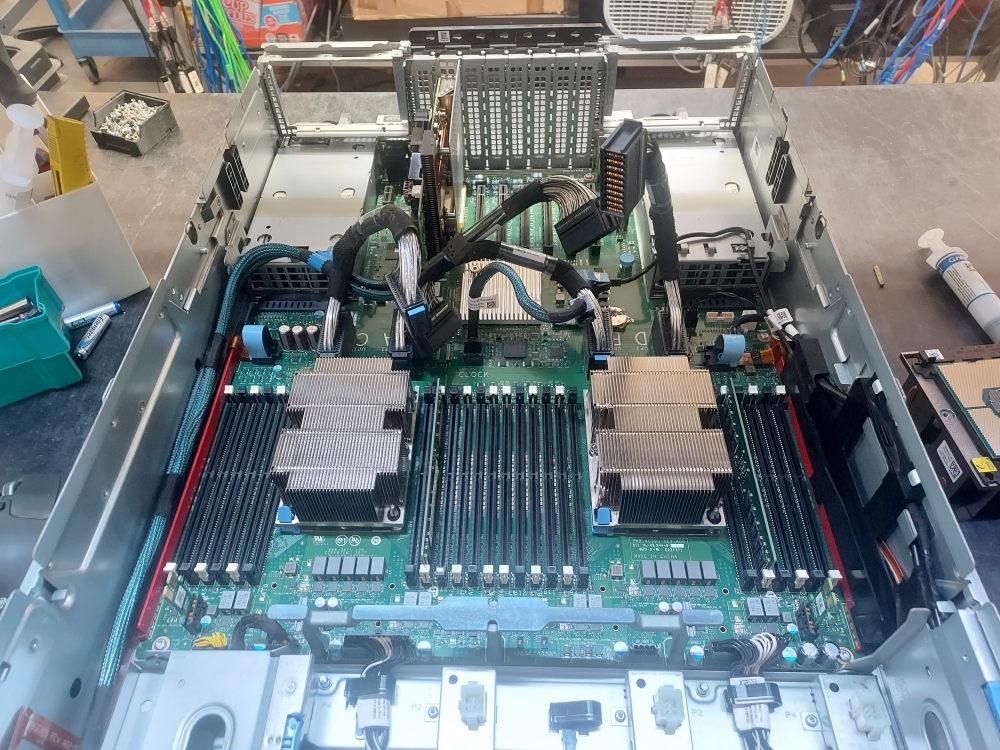
You will also need to remove the fan assembly cage:
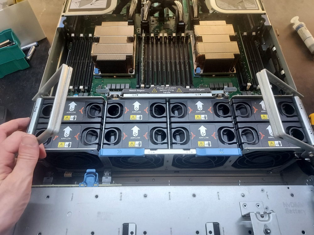
Remove the heatsinks to expose the CPU socket. Take this opportunity to inspect the CPU pins for damage and to blow out any dust or debris with an electric blower or compressed air.
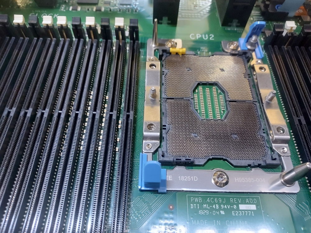
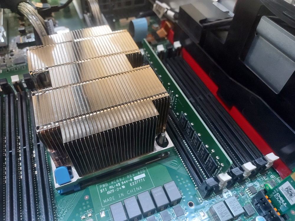
Align the arrow on the corner of the CPU with the arrow on the motherboard and carefully place the CPU in the socket. You can also install the CPU into the heatsink first. I prefer this method. Often times the black plastic CPU retaining brackets become brittle from years of heat exposure. When you flip the heatsink over to install it over the socket, the CPU can fall out and damage the pins.
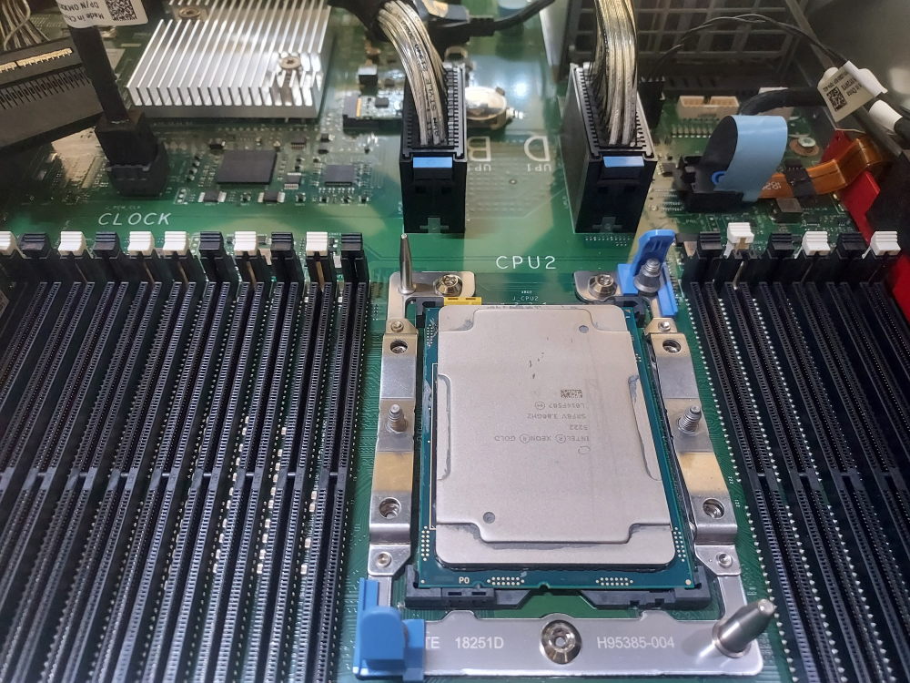
Apply thermal paste:
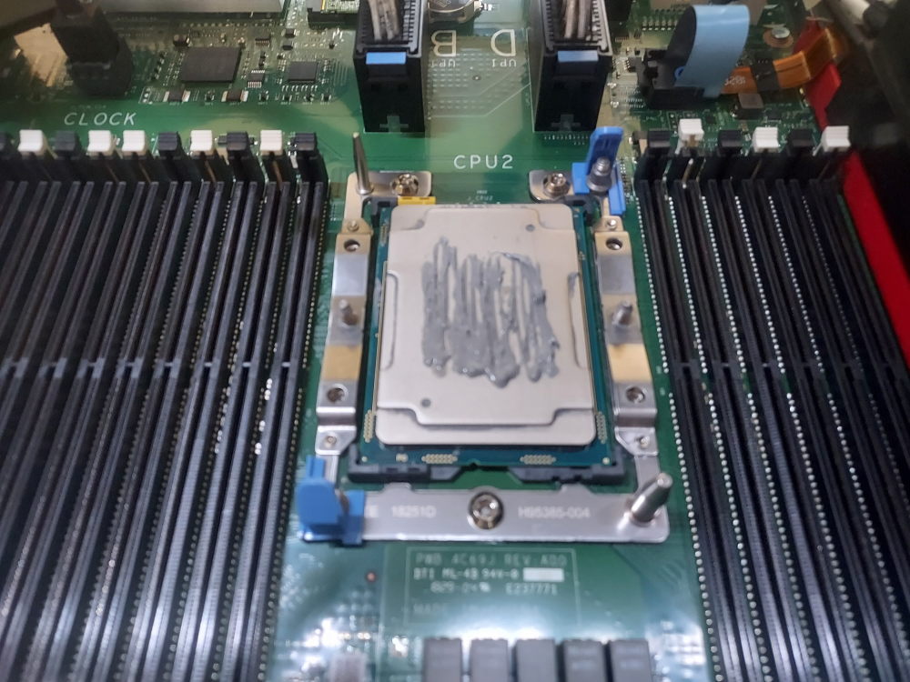
Finally, snap on the heatsink and tighten down the T30 screws.
Installing the memory
Each CPU in the PowerEdge 940 has 12 memory slots. The population rules are similar to other Dell servers. The main idea is spreading the memory across as many channels as possible and mirroring the configuration across CPUs. Always populate the white slots first. Each white slot represents a channel. Only after populating the white slots can you begin populating the black slots which represent the second DIMM for the channel. If you populate A1 it’s best practice to populate B1. Because this is a 4 CPU system you will also have slots labeled C and D. These will be located on the processor expansion module.
R940 memory population chart
| DIMMs per CPU | CPU 1 | CPU 2 | CPU 3 | CPU 4 | Total (4 CPUs) |
|---|---|---|---|---|---|
| 1 DIMM | A1 | B1 | C1 | D1 | 4 DIMMs |
| 2 DIMMs | A1, A2 | B1, B2 | C1, C2 | D1, D2 | 8 DIMMs |
| 4 DIMMs | A1, A2, A4, A5 | B1, B2, B4, B5 | C1, C2, C4, C5 | D1, D2, D4, D5 | 16 DIMMs |
| 6 DIMMs | A1, A2, A3, A4, A5, A6 | B1, B2, B3, B4, B5, B6 | C1, C2, C3, C4, C5, C6 | D1, D2, D3, D4, D5, D6 | 24 DIMMs |
| 8 DIMMs | A1, A2, A4, A5, A7, A8, A10, A11 | B1, B2, B4, B5, B7, B8, B10, B11 | C1, C2, C4, C5, C7, C8, C10, C11 | D1, D2, D4, D5, D7, D8, D10, D11 | 32 DIMMs |
| 12 DIMMs | A1–A12 | B1–B12 | C1–C12 | D1–D12 | 48 DIMMs |
R940 channel layout
| Channel | CPU 1 | CPU 2 | CPU 3 | CPU 4 |
|---|---|---|---|---|
| Channel 0 | A1 / A7 | B1 / B7 | C1 / C7 | D1 / D7 |
| Channel 1 | A2 / A8 | B2 / B8 | C2 / C8 | D2 / D8 |
| Channel 2 | A3 / A9 | B3 / B9 | C3 / C9 | D3 / D9 |
| Channel 3 | A4 / A10 | B4 / B10 | C4 / C10 | D4 / D10 |
| Channel 4 | A5 / A11 | B5 / B11 | C5 / C11 | D5 / D11 |
| Channel 5 | A6 / A12 | B6 / B12 | C6 / C12 | D6 / D12 |
Installing the NDC
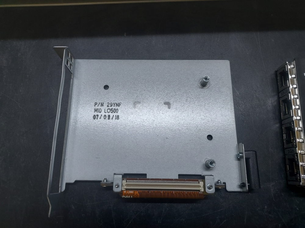
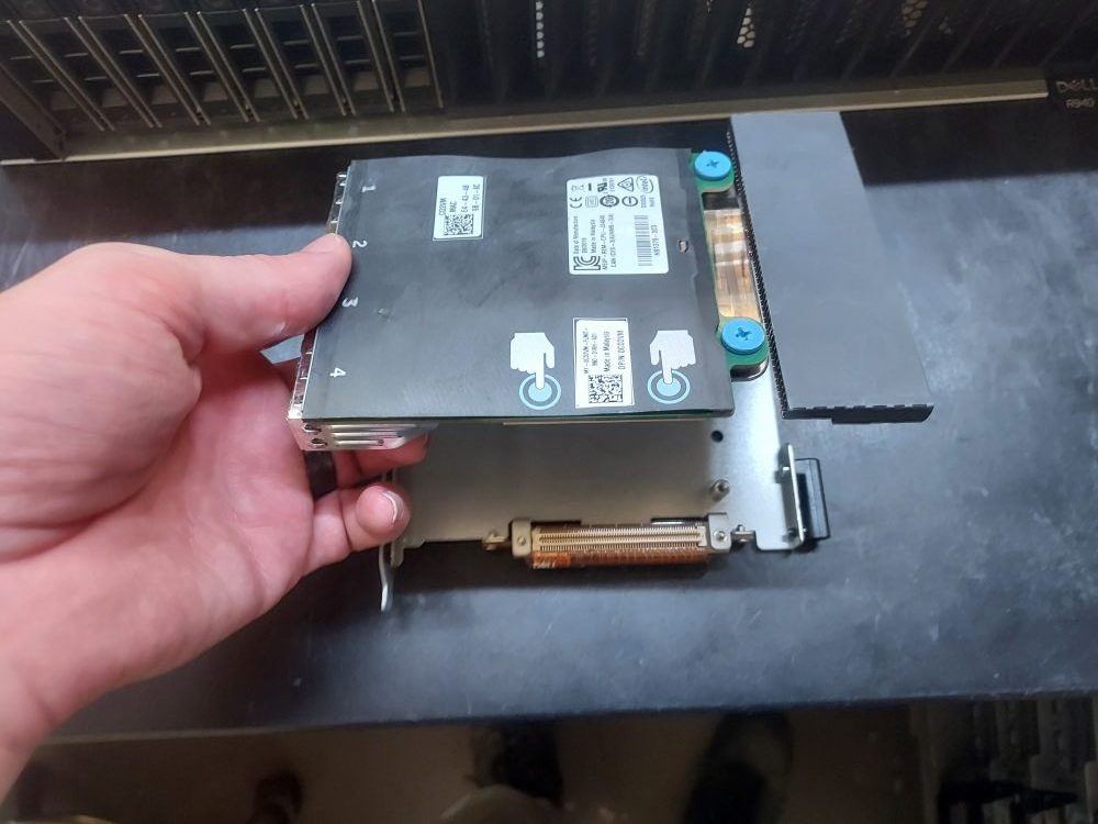
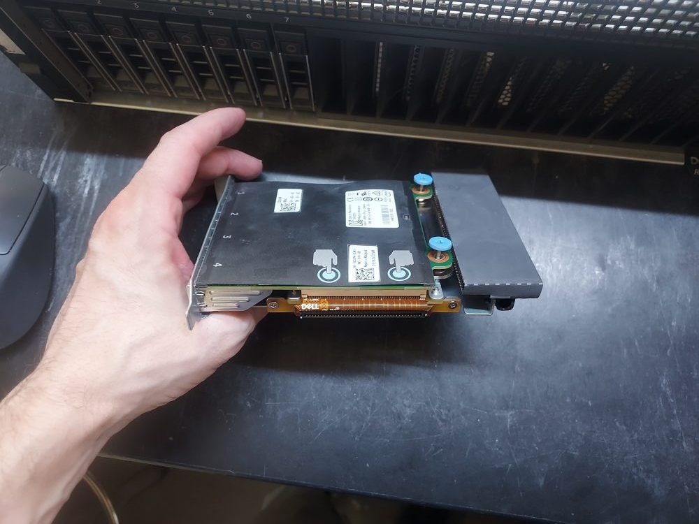
On the R940 the NDC first installs into this bracket. The bracket (also called the rNDC bracket) then interfaces with the mezzanine port on the motherboard.
Installing a RAID/HBA controller
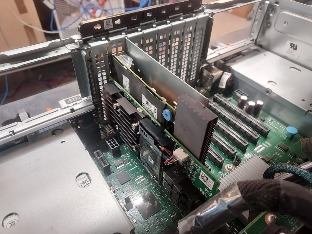
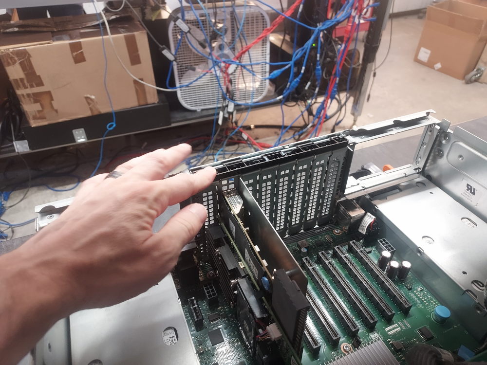
The RAID or HBA controller will also install in the rear of the server directly in a PCIe slot. Be sure you have the correct SAS cable. This cable will route from the 8 bay SFF backplane, to the left side of the chassis, and finally to the rear expansion slots. You will need a full height bracket for any PCIe card you have.
This is the required cable. One end will plug into the backplane. The other end goes to the storage controller.
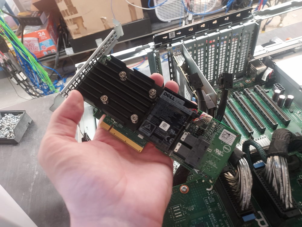
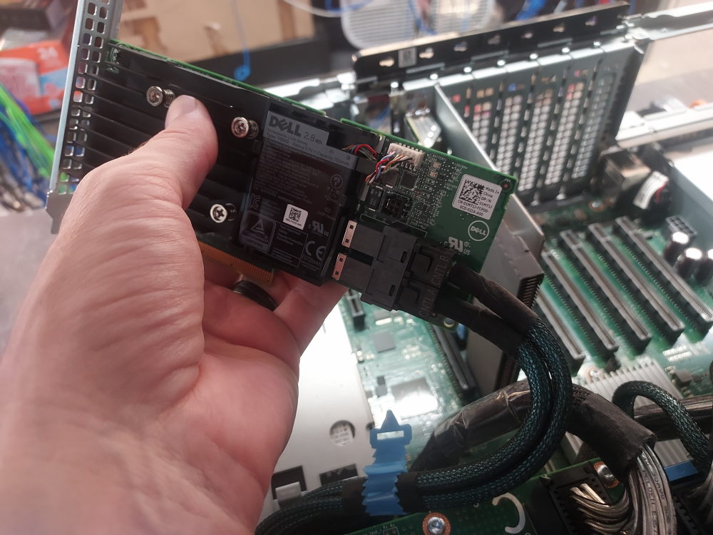
The rear expansion ports are locked in by a black plastic mechanism. Slide the mechanism and then lift. Once the card is installed lock the mechanism back into place.
Installing the processor expansion module
Now it’s time to install the mezzanine for processors 3 and 4. Because it blocks the installation path for the other components it is best to install this piece last. Populate the processors and memory in the exact same way you did for processors 1 and 2. You can do this when the module is out of the server or you can install the module first and then put in the processors and memory.
Before you install the module you should plug in the required UPI cables. Installing the module first will make plugging these cables in more difficult than it needs to be. There are 4 in total. The connection only goes in one way so make sure you orient them properly. On the motherboard you will see connectors for UPI cables A, B, C, and D.
In the image below you will see the 4 UPI cables. Also make note of the clock cable.
With the clock and UPI cables plugged in it’s time to install the processor expansion module.
Lift the module using the handle on the front and guide it down to its installation point. On the rear corners of the module you will see the hinging mechanism. This latches on to the chassis.
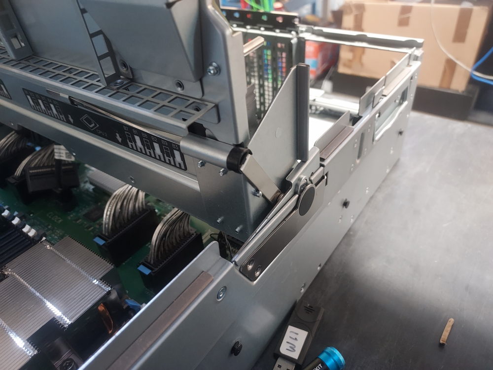
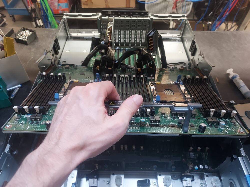
At the bottom make sure you have the following component installed. When rotated down into position the expansion board comes into contact with these 2 small chips:
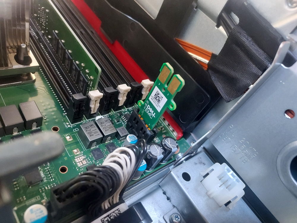
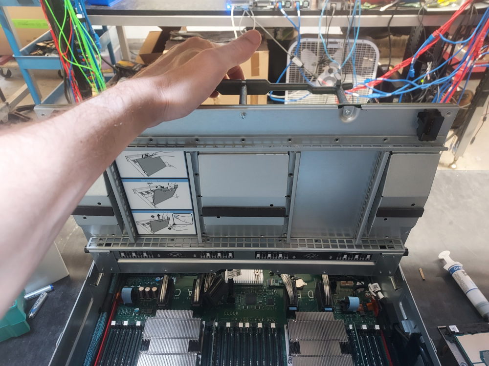
Make sure the expansion board can easily hinge up and down. You shouldn’t encounter any resistance except from the weight of the board itself.
Now plug in the UPI cables that you previously attached to the motherboard. They are assigned letters. Simply match up the letters. You will notice the cables cross over each other. It is helpful to have the expansion board in its fully upright position while plugging in the cables.
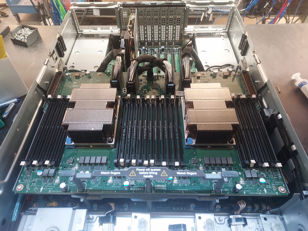
Once you have the cables plugged in carefully bring the expansion board down to its natural sitting position.
Installing the risers
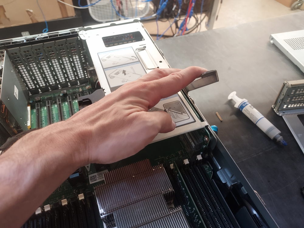
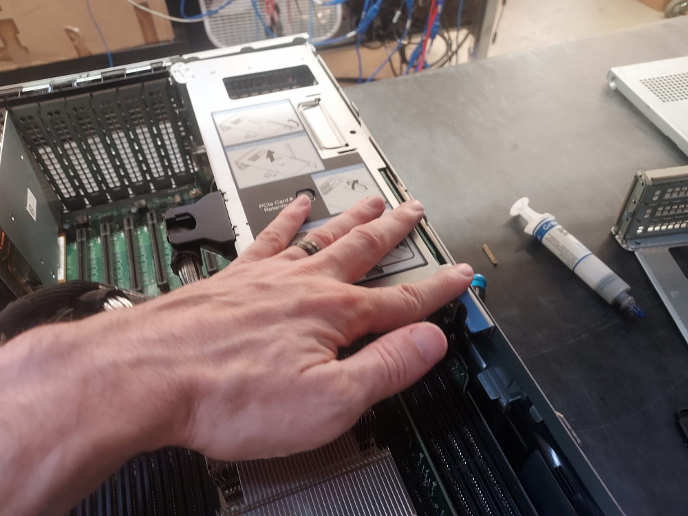
One of the last components to install are the risers. These plug in to the processor expansion module. There is a left riser and a right riser. Both have a gear-like mechanism that pulls them up or down into position and securely connects them to the riser connector.
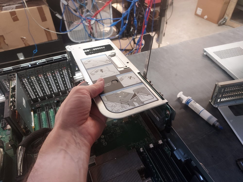
Installing power supplies
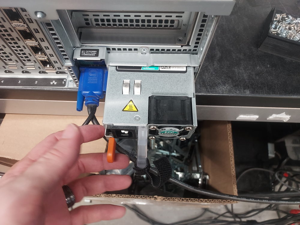
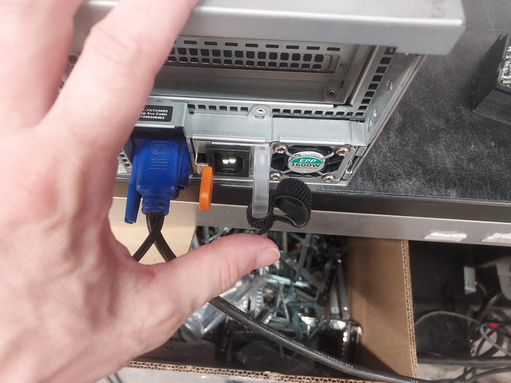
Last and certainly not least are the power supplies. They slide in through the rear of the chassis like most PowerEdge servers.
Final picture
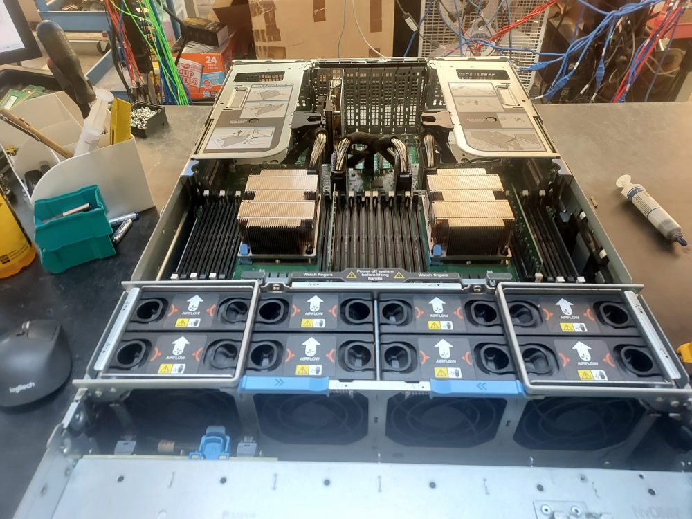
Here is the complete build. I do believe there is an air shroud that can be installed but I didn’t have one on hand for this particular server.
Leave a Reply