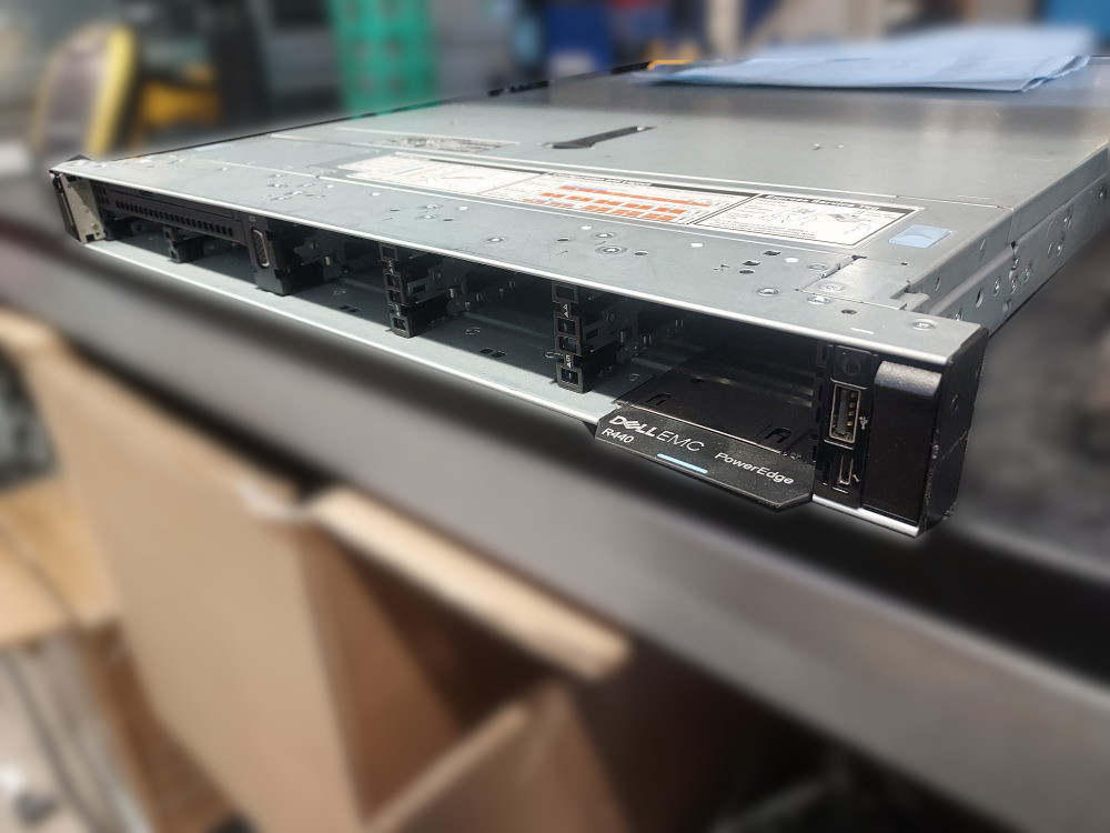
The Dell PowerEdge R440 is a 1U server designed for Intel Xeon Scalable processors. The platform is available in several storage and PCIe configurations. The server we’ll focus on today is the Dell PowerEdge R440 8 Bay Small Form Factor, which supports up to eight 2.5-inch SAS or SATA drives through the front drive bays.
This guide covers the major components required to assemble an R440 8 Bay from an empty chassis, including the motherboard, storage backplane and cabling, cooling system, and PCIe risers.
Essential Components
Before you begin assembling an R440 8 Bay from an empty chassis, it is important to identify the hardware required to turn the chassis into a functioning server. This section covers the major components that should be installed and verified before moving on to the rest of the build.
The goal is to start with a bare chassis and make sure you have everything necessary to power the system on, recognize the installed hardware, and eventually install an operating system.
For a complete list of compatible R440 parts and components see this page.
Motherboard
The motherboard should already be installed in the chassis and securely fastened in place. It serves as the central connection point for the server’s processors, memory, storage, expansion cards, cooling system, and power delivery.
The processors and memory modules are installed directly onto the motherboard, while the power supplies connect through the rear of the chassis to the R440 power distribution board. PCIe risers attach to the motherboard to provide expansion slots, and the front storage backplane connects to the system board and storage controller. The hot-swap fan modules also connect directly to the motherboard.
Before installing additional components, make sure the motherboard is properly seated and secured inside the chassis.
Backplane and Cables
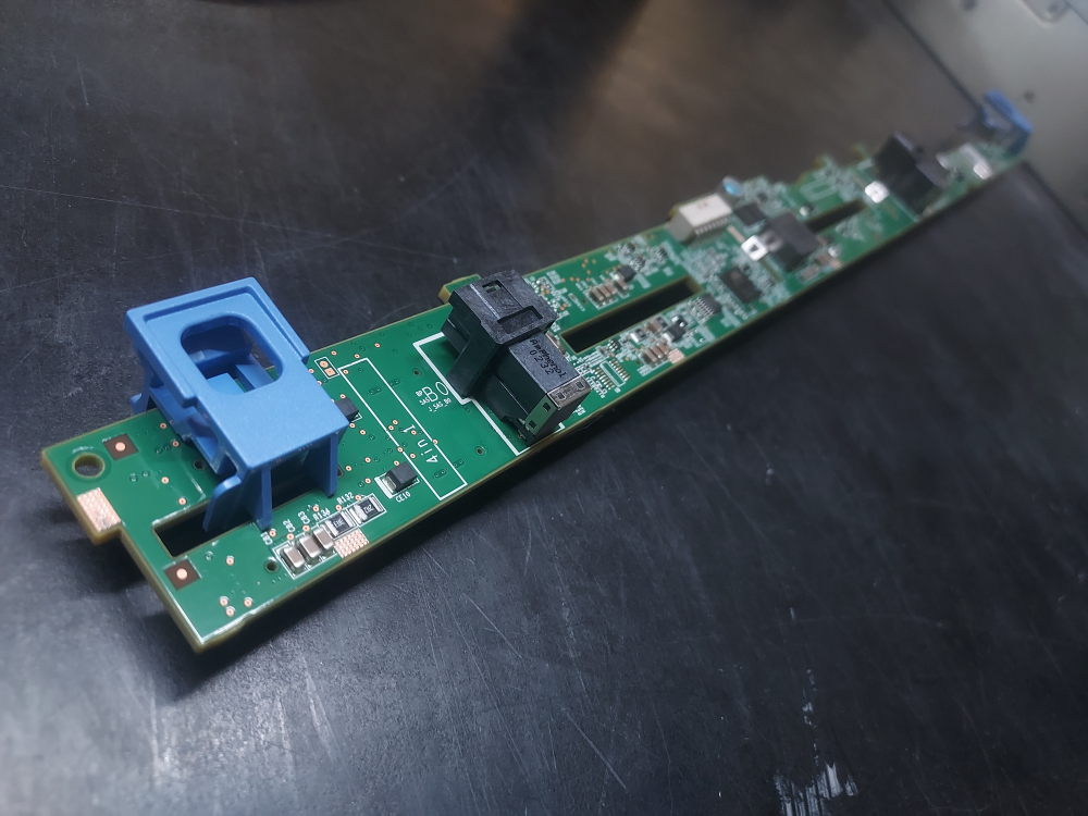
The front storage backplane is a critical component of the R440 8 Bay configuration. It provides the connections required for the front-mounted drives to communicate with the server’s storage controller while also supplying power to the drive bays.
The backplane requires the appropriate signal and power connections, along with the SAS connection to the RAID or HBA controller. This is the required signal cable for the backplane. The signal cable connects the backplane to the motherboard.
The power cable for the backplane is supplied by the power distribution board.
For the 8 Bay SFF backplane you’ll need this SAS cable if you’ll be using a standard PCIe RAID or HBA controller from Dell. There is also a cable compatible with the H750 controller. The H750 has a different connector compared to controllers like the H730P or the H740P. Select the right cable for your particular controller.
Please note – the R440 does not support a Dell mini mono RAID/HBA controller like many other platforms in the same generation.
Before proceeding with the build, inspect the backplane and verify that all required signal, power, and storage-controller connections are present and properly seated.
Cooling
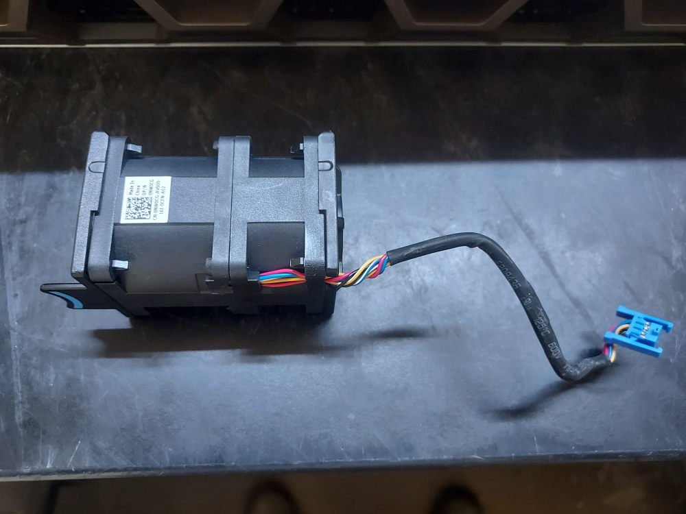
The R440 uses a combination of fan modules, processor heatsinks, and an air shroud to maintain proper operating temperatures. These components work together to move airflow through the 1U chassis and remove heat from the processors, memory, and other internal hardware.
The R440 uses 6 fans to push air through the system. These fans are not hot swappable nor are they modular like the fan design of the R640. The fans connect to the motherboard via cable and the system should be powered off if you need to change them. The fans come in both a standard and high performance variation.
The processors also require compatible heatsinks. A system with two processors will require two heatsinks. On the R440 the heatsinks for CPU1 and CPU2 are not interchangeable. This is the heatsink for CPU1 and this is the heatsink for CPU2.
The final major cooling component is the air shroud. Positioned over the motherboard, the shroud directs airflow from the fan modules through the processor and memory areas. Operating the server without the appropriate shroud can disrupt the intended airflow pattern and reduce cooling performance.
The fan modules, processor heatsinks, and air shroud should all be considered essential parts of the R440’s thermal management system.
Risers
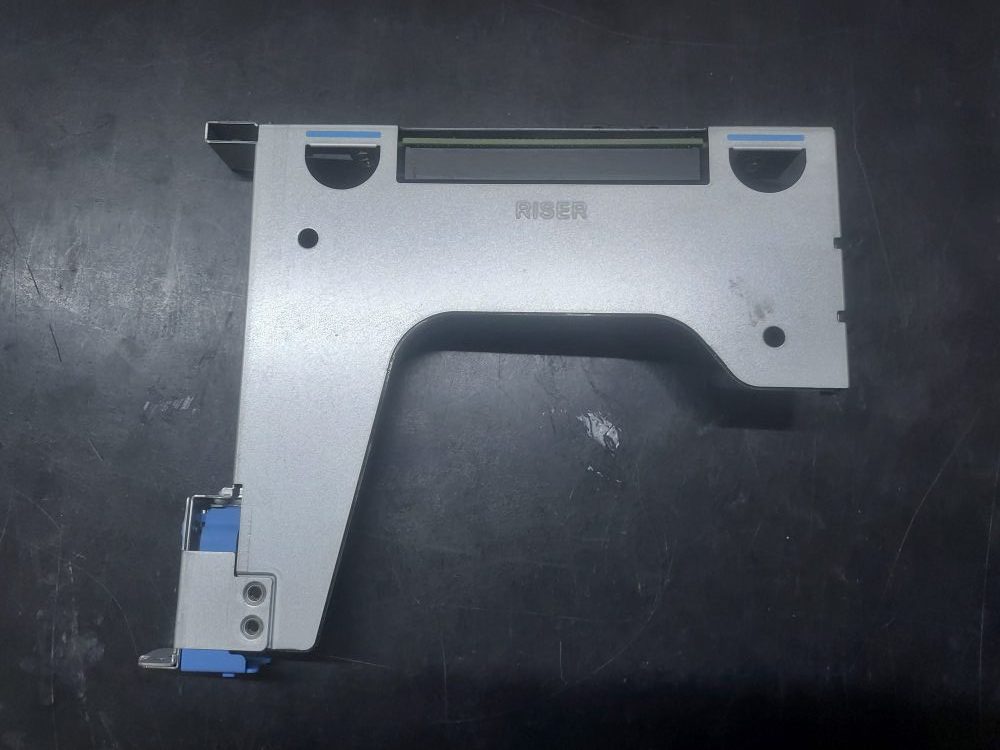
The R440 has a relatively simple PCIe riser system compared with larger PowerEdge platforms. There are 2 different chassis variations. One variation supports a single full-height riser in the rear (see picture above.) The other chassis variation supports 2 low-profile risers in the rear. Both variations support the internal riser designed for a PCIe RAID/HBA controller.
The following build guide will be focused on the chassis variation with the full-height riser.
If I ever get access to the 2 riser chassis I will update the guide.
Here is a breakdown of general riser terminology:
- LP (Low Profile) refers to the height of the expansion card.
- FH (Full Height) refers to the taller standard-height card.
- HL (Half Length) refers to the front-to-back length of the card.
For example, an FHHL card is full-height and half-length, while an LPHL card is low-profile and half-length.
Another note if you have the 2 rear low-profile riser chassis – the left and right low-profile risers are not interchangeable. Although both accept low-profile, half-length cards, they are different assemblies and connect to different processor PCIe resources.
Building the server
You will need the following tools to complete this build:
- Torque #30
- Phillips #2
- Compressed air
- thermal paste
Installing the processors
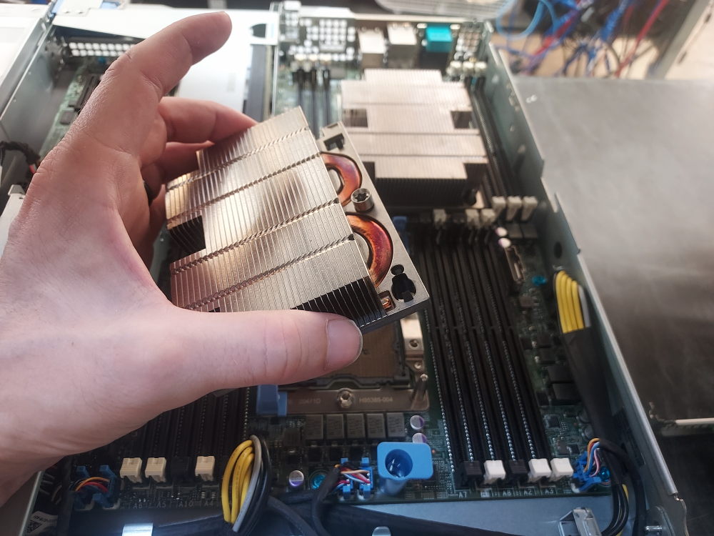
Remove the lid to the server and remove the air shroud. Remove the heatsink of CPU1 to expose the CPU socket. Press inward on the blue plastic retaining clips. Do not be alarmed if they snap off or break. This is common after years of heat exposure and they aren’t entirely necessary.
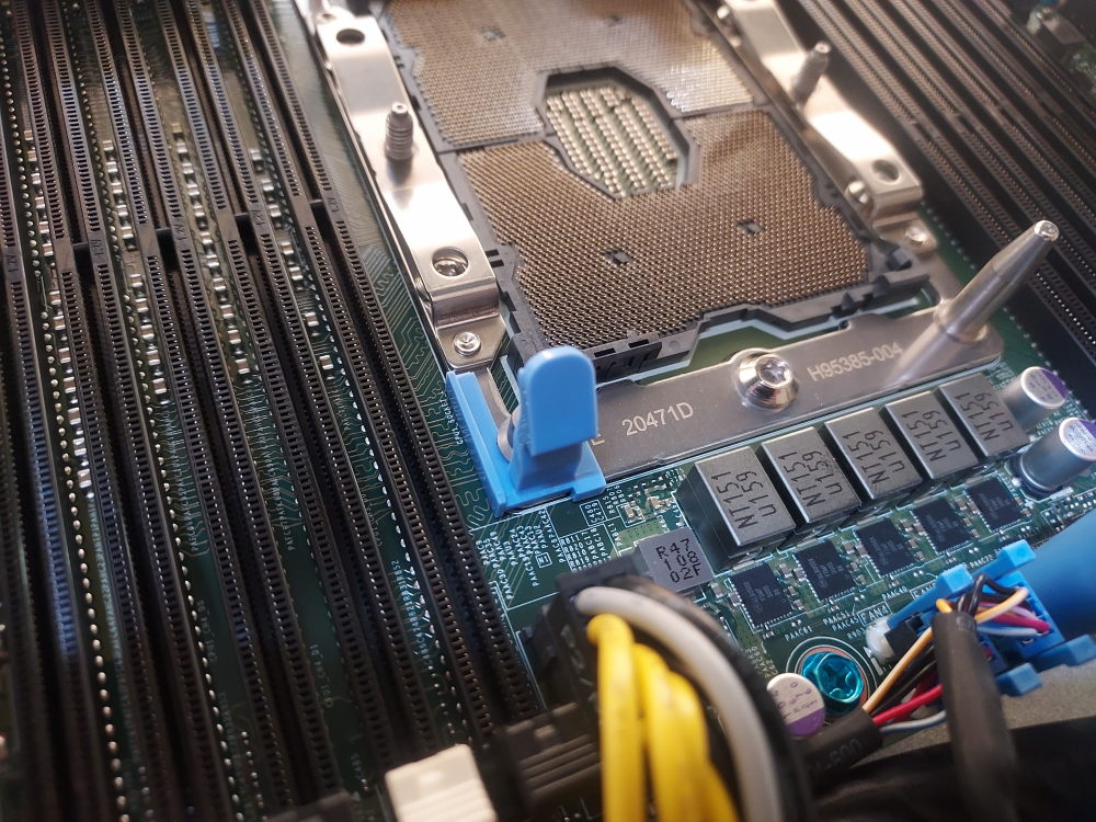
Visually inspect the CPU pins. None of them should be bent. Blow out any dust or debris with a can of compressed air or electric blower.
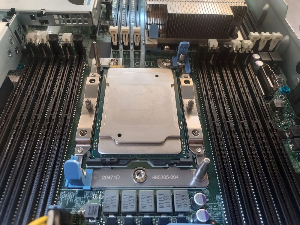
Carefully place the CPU in the socket. Make sure the arrow on the CPU is oriented with the arrow on the motherboard.
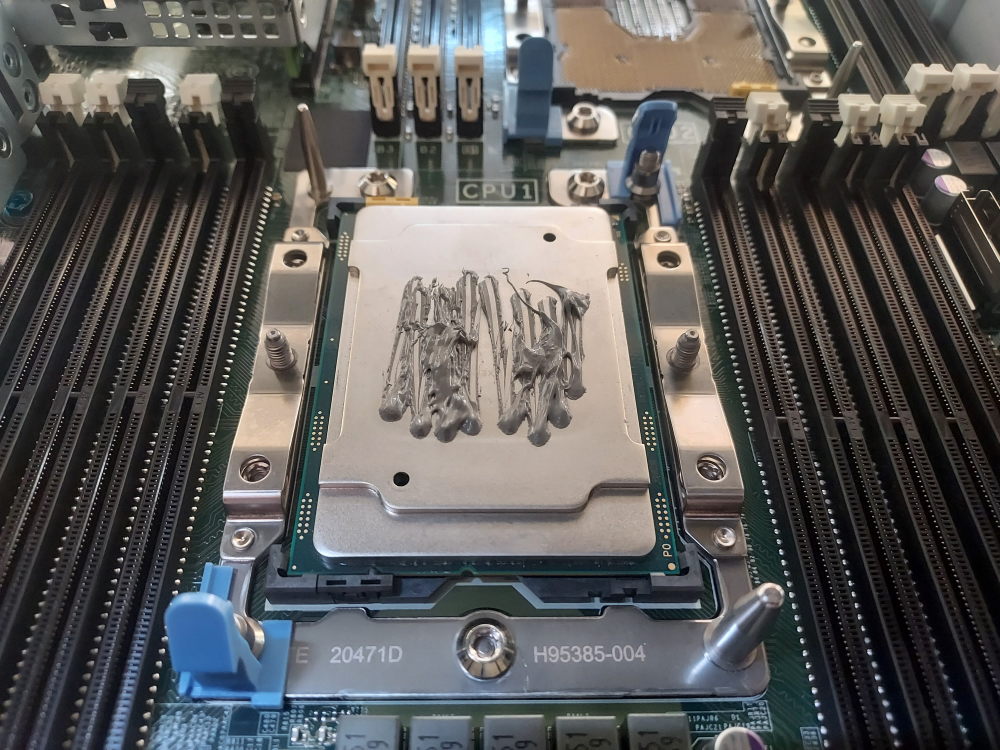
Apply thermal paste. Please excuse my messy application on this one (:
Place the heatsink over the CPU and press firmly until you hear the black plastic CPU retaining bracket snap into place. Screw down with a T30 bit.
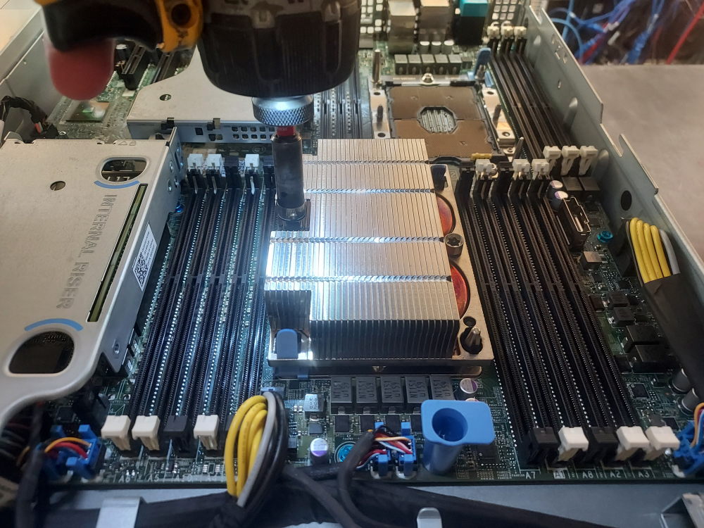
Follow the same procedure above to install CPU2.
Installing memory
Dell went with a curious memory arrangement for the R440. There are 10 DIMM slots assigned to CPU1 yet only 6 assigned to CPU2. The memory configuration rules remain similar to other servers of the same platform – spread your memory across as many channels as possible and mirror the configuration across both processors. If you populate DIMM A1 be sure to populate DIMM B1 (for a 2 CPU configuration) The R440 has a total of 6 channels per CPU. Each channel is represented by the white DIMM slots. Secondary slots for the channel are represented by the black slots. Always populate the white slots first.
Here I have just 2 sticks of RAM so I’ll populate DIMMs A1 and B1. You could just as easily populate DIMMs A2 and B2. The point is to mirror the configuration and use as many channels as possible.
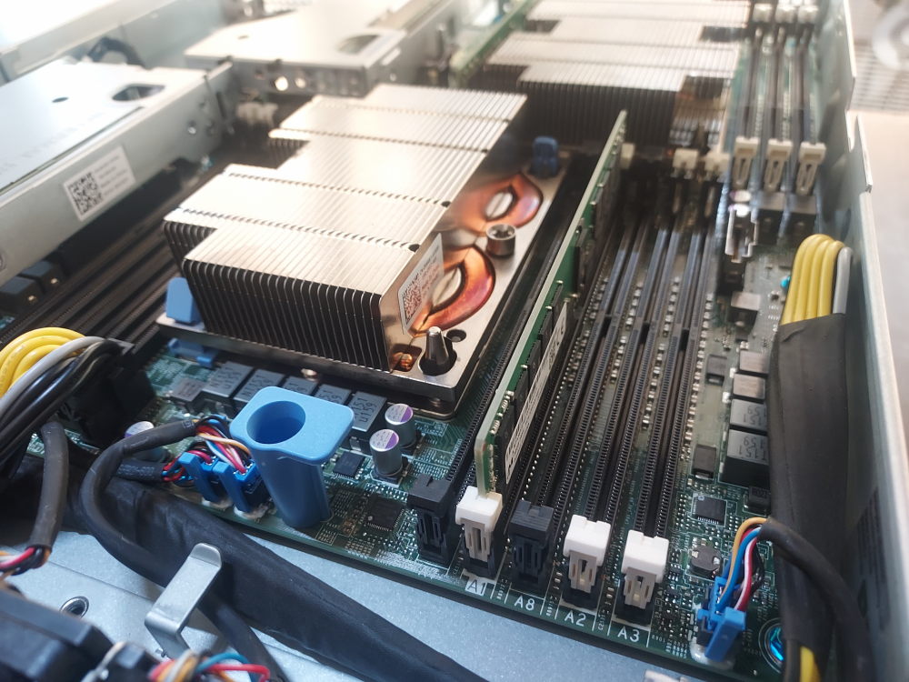
Click to see PowerEdge R440 channel layout
CPU1:
- A1 / A7 = Channel 0
- A2 / A8 = Channel 1
- A3 = Channel 2
- A4 / A9 = Channel 3
- A5 / A10 = Channel 4
- A6 = Channel 5
CPU2:
- B1 = Channel 0
- B2 = Channel 1
- B3 = Channel 2
- B4 = Channel 3
- B5 = Channel 4
- B6 = Channel 5
Installing the RAID/HBA controller
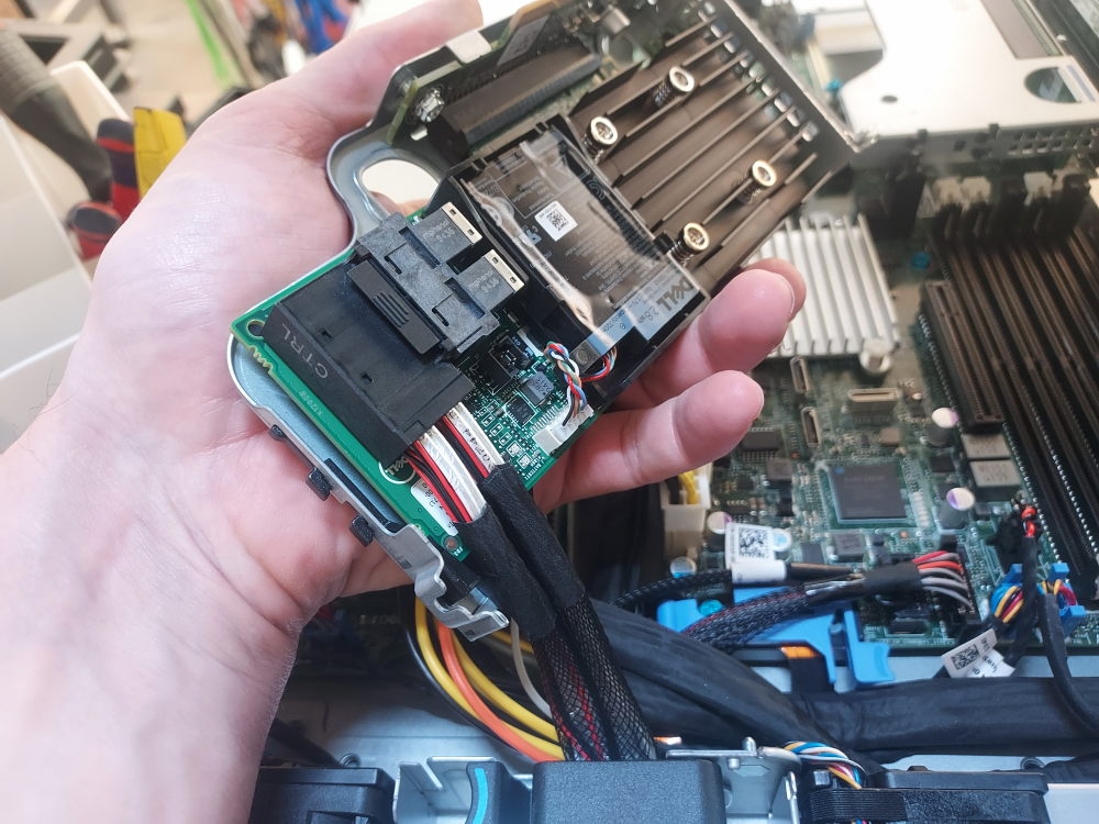
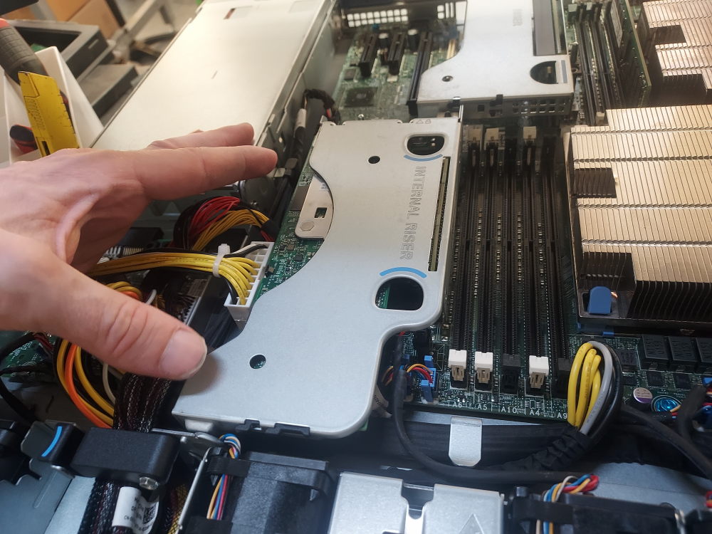
Near the center left of the chassis you will see the low profile internal riser. This where the storage controller will install. The storage controller will need a low profile bracket. I find it is easier to first remove the internal riser, connect the storage cable to the storage controller, install the controller into riser, and finally install the riser back on the motherboard.
The first thing you need to do is ensure the storage cable is properly plugged into the backplane and routed in a way that reaches the internal riser.
2 mini SAS HD connectors labeled A0 and B0 connect to the backplane:
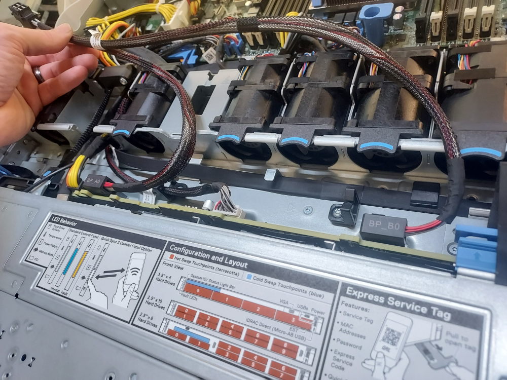
The cable routes through this part of the server.
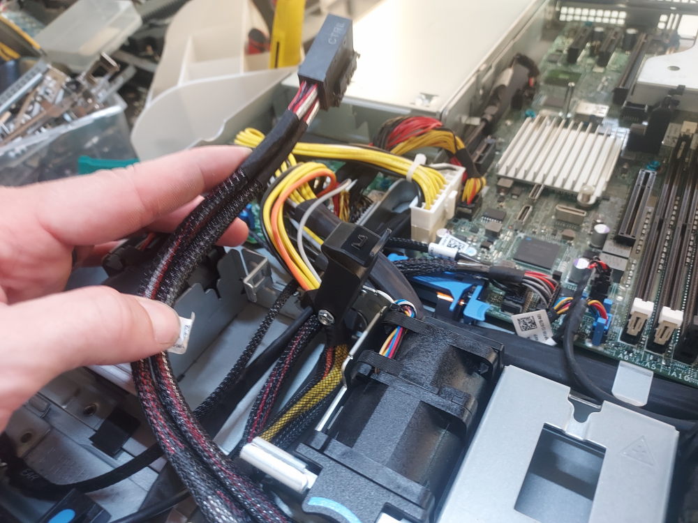
Remove the riser. There is a small blue locking mechanism that must be switched before removing.
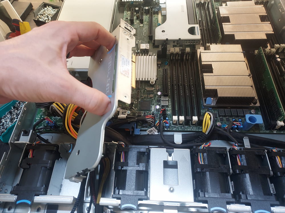
Install the controller into the riser.
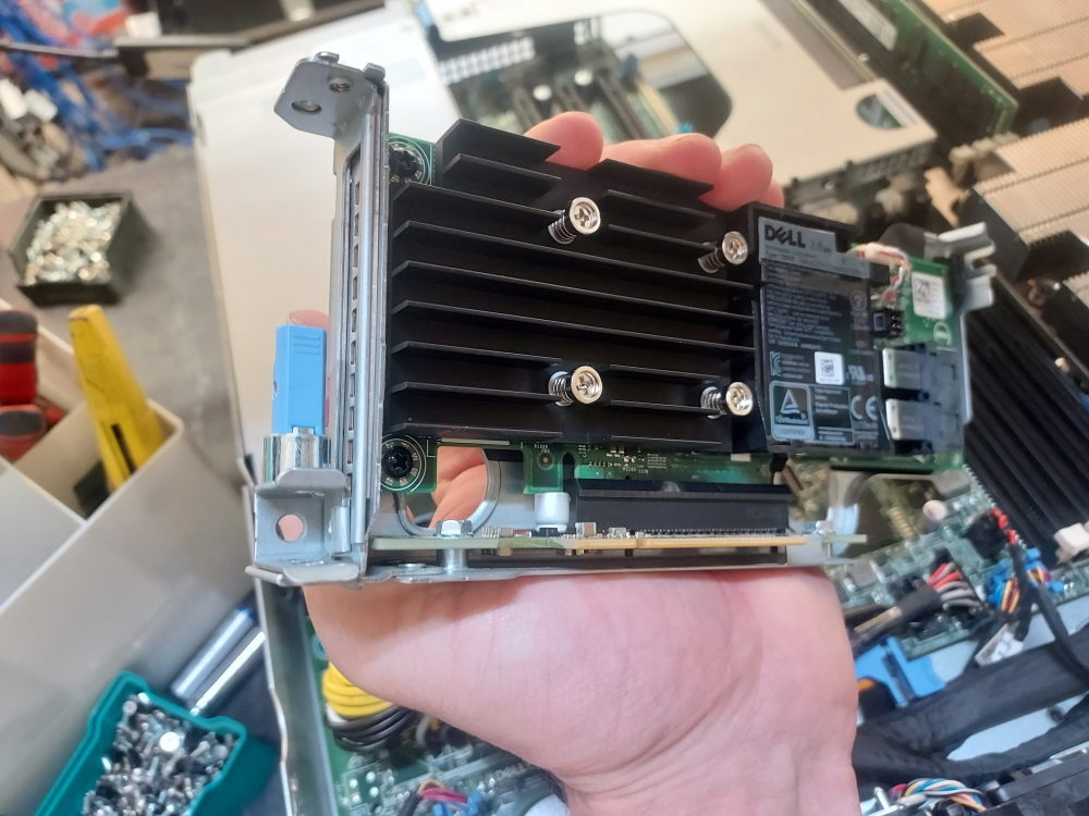
Plug in the SAS cable:
Reinstall the riser:
Installing the LOM/OCP riser
The R440 supports various compatible OCP network cards that DELL (somewhat confusingly) calls the LOM riser. The card installs into the OCP mezzanine port at the rear of the server.
Remove the riser(s) to access the installation point:
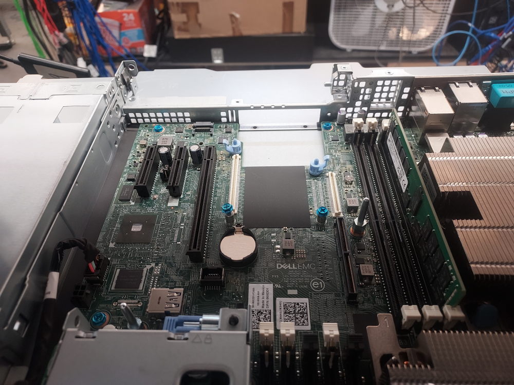
Remove any screws present in the mounting holes:
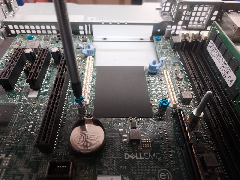
Line up the connectors. The card will have holes that align with the blue pegs seen on the motherboard:
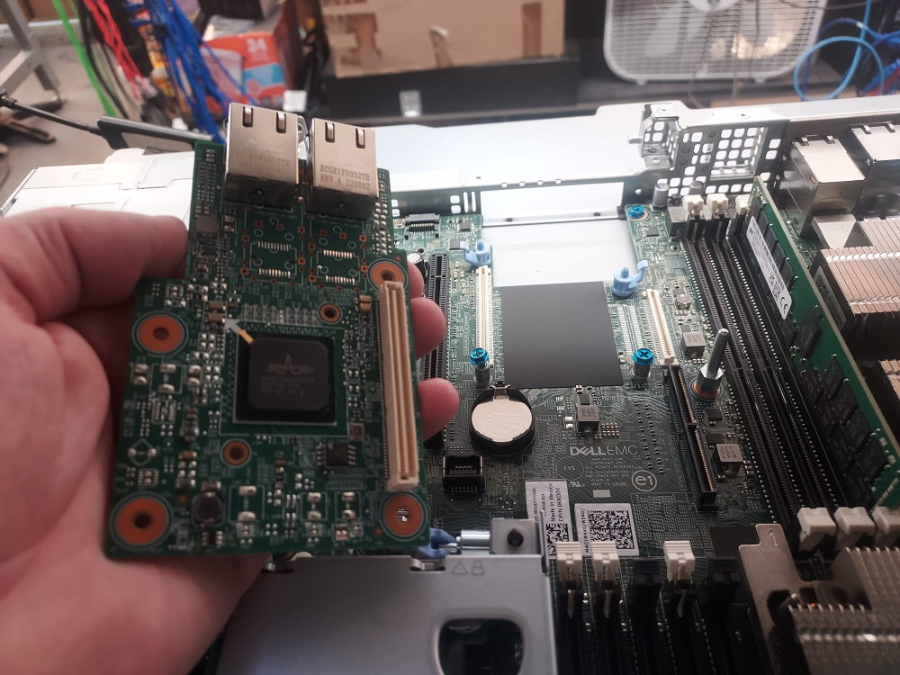
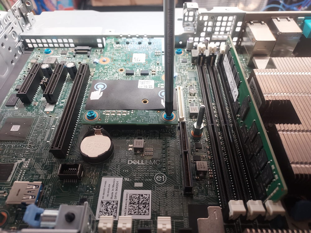
Insert the ports through the rear bracket and then snap the card into place. Secure the card with 2 screws using a phillips #2 bit:
Installing the rear riser(s)
Now that the OCP networking card is installed you can reinstall the riser. As mentioned in the beginning, the particular chassis in this guide is setup for a single full-height riser. There is also a chassis variation that has 2 low-profile risers rather than one full-height.
Now is the time to install any PCIe devices you’d like:
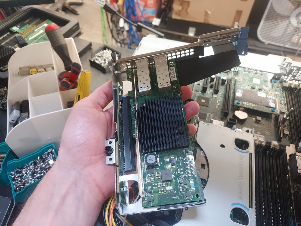
Take note of the alignment peg:
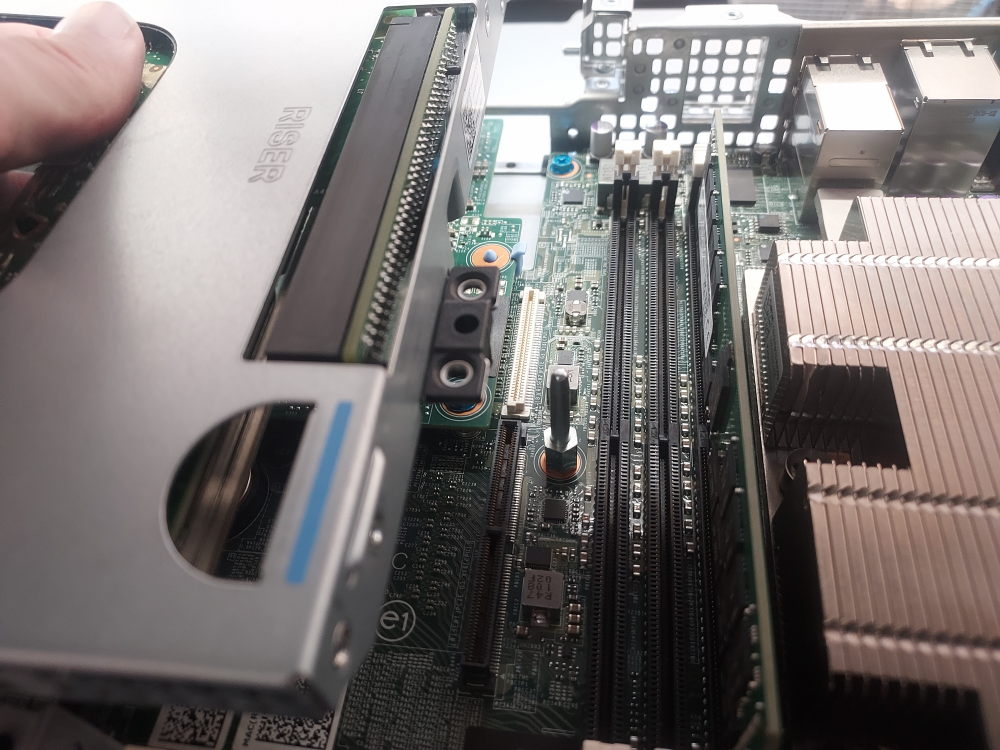
Snap the riser into place:
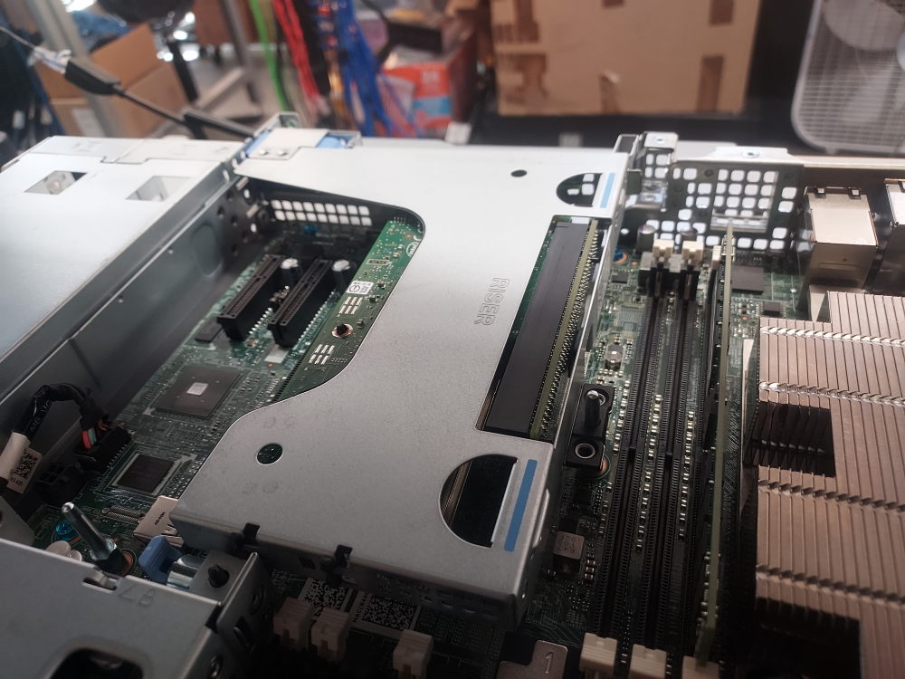
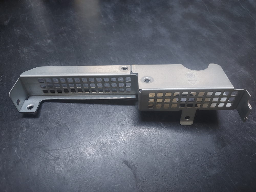
If you do not have any risers or you do not require any additional PCIe slots, you can install the rear filler in place of the risers. This ensures proper air flow and prevents debris from entering the server where it can restrict airflow or cause damage.
Installing the power supplies
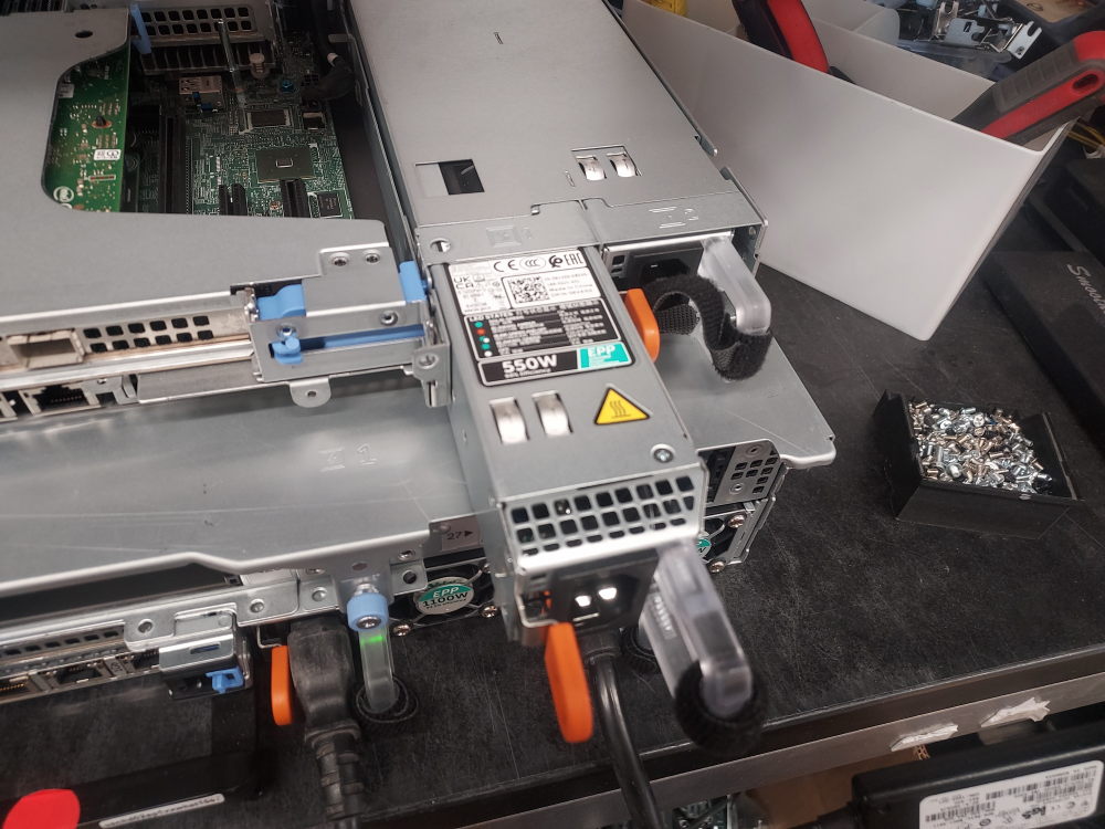
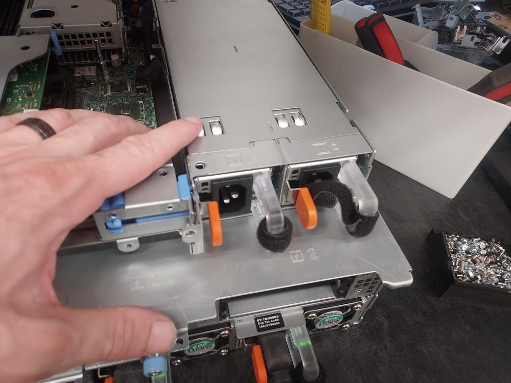
The power supplies install in the rear of the server:
Complete build photo
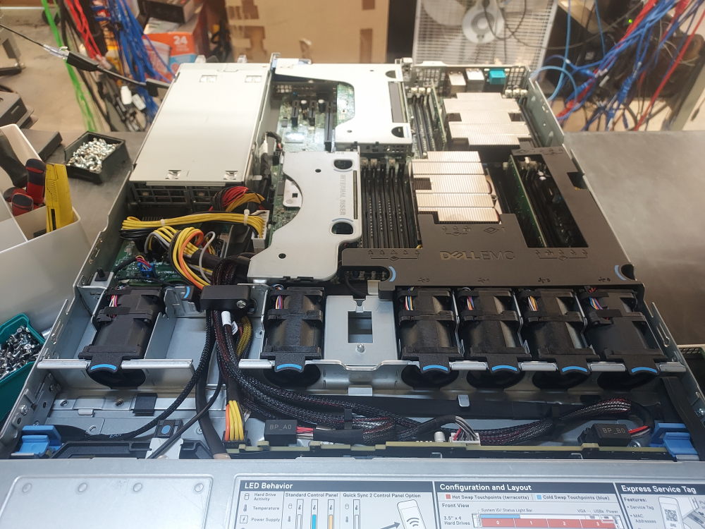
At this point reinstall the air shroud. The build is done and should look similar to the image below:
Leave a Reply