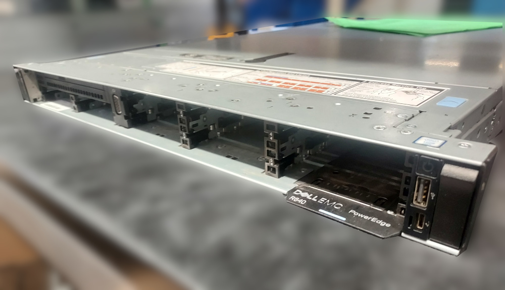
The Dell PowerEdge R640 8 bay is a 1U chassis outfitted with 8 SFF SAS/Sata drive bays. The platform supports both generation 1 and generation 2 Intel Xeon Scalable processors as well as DDR4 ECC RDIMMs and LRDIMMs. This particular chassis has rather simple configuration options compared to its 10 bay older brother, which supports u.2 NVME drives. The 8 bay chassis has no support for NVME in the front drive bays due to no built in connections on the backplane.
In the rear the most common configuration is 3 half height expansion slots supported by risers 1 and 2 but Dell did make a chassis with 2 full height slots. Both of these configurations require different risers.
Essential components
If you’re building this server from the ground up you should first verify a few critical components required. These guides are written for someone who has a chassis in front of them, needs to get the chassis operational, but has almost no clue what he’s looking at or what is required to boot a functional environment.
Motherboard
The chassis should obviously have the motherboard screwed in. This is the primary hub where everything else feeds in. The power supplies will connect to the board from the rear, Both processors and memory will be installed on the board, the risers connect into the appropriate slots, the backplane will be wired up so you can stick drives through the front, and of course the hot swap fans will go straight into the motherboard. Verify the board is in the husk of the chassis.
Backplane and required cables
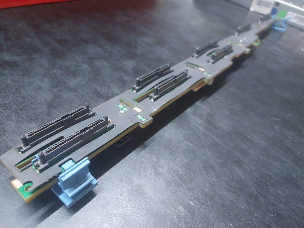
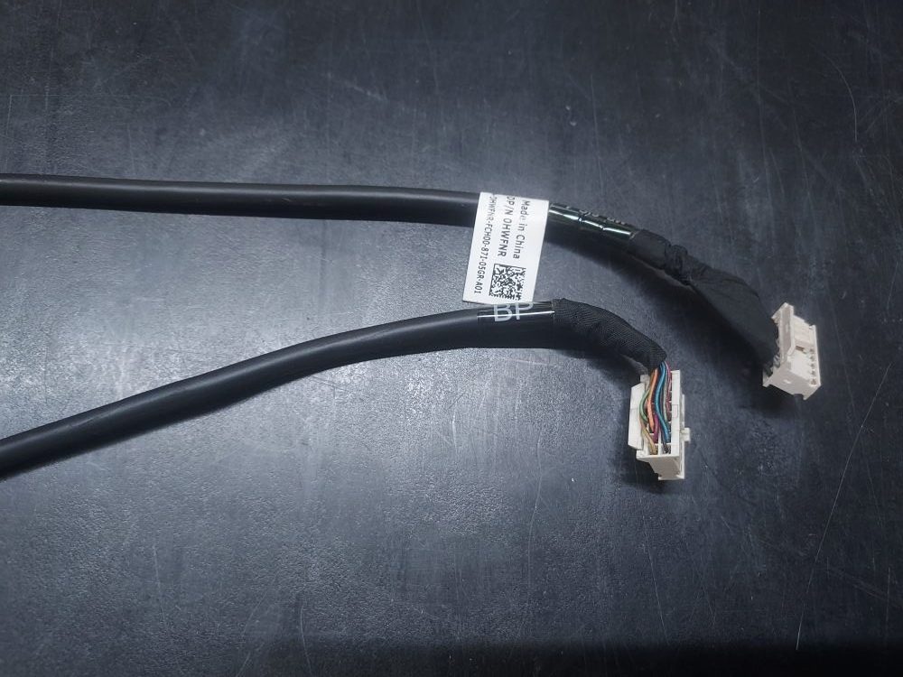
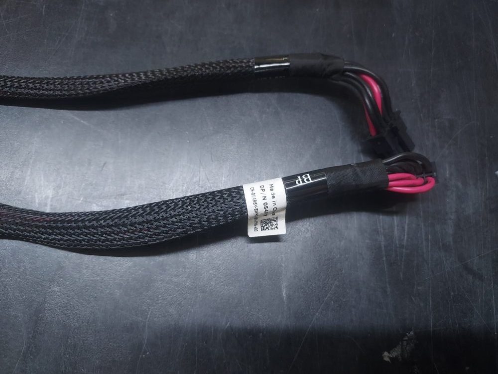
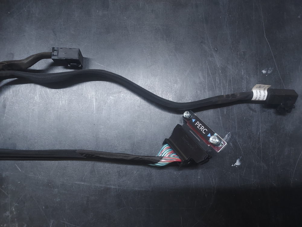
The second perhaps not so obvious piece of hardware is the backplane and the 2 required cables needed to connect the backplane to the motherboard. In most cases, any backplane (this includes rear flex bay backplanes as well) will have 3 required cables. The first cable is a signal cable, the second cable is a power cable, and the third cable will be a SAS PERC cable used to connect the backplane to a RAID/HBA controller. With this particular chassis you will most likely be using one of Dells PERC cables to attach a mini mono RAID/HBA controller. Take a look at the backplane and ensure all 3 cables are present. Without all 3 you will not have the ability to configure any kind of storage arrays.
Click to see picture of backplane
Click to see picture of signal cable
Click to see picture of power cable
Click to see picture of PERC cable
Cooling
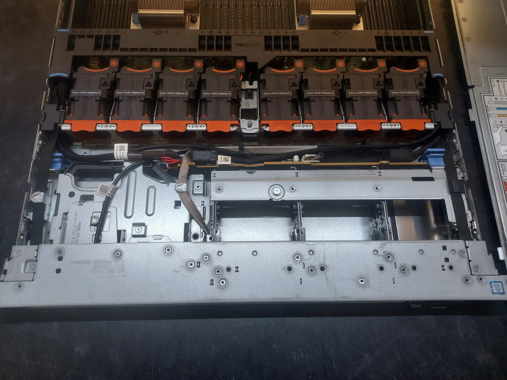
There are a number of critical components the server needs for proper cooling and thermal regulation.
The first main component is of course the fans identified by the orange highlights. In general, the color orange indicates that a particular component is able to be hot swapped.
These are partially slotted in to fixed positions on the server chassis and then connect to the motherboard through a set of pins. There are 2 variations of fans – standard performance and high performance. Certain configurations may require high performance fans. If you’re using a CPU with a TDP higher than 165 watts they come recommended. Otherwise, standard performance will work. Either way you want to make sure the server has all 8 fans installed otherwise the server will not only complain and generate logs but you may run into serious thermal issues.
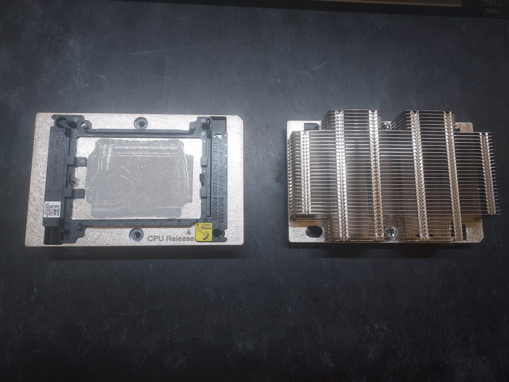
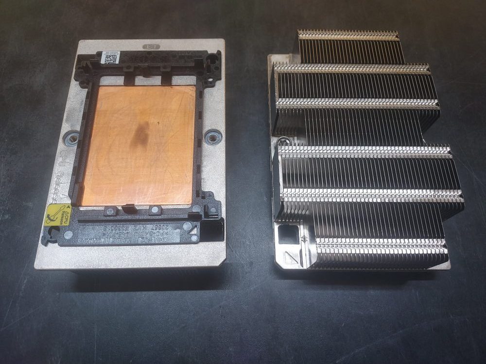
Another component critical for cooling is the heatsink. You will need 2 of these if you have 2 processors. These also come in standard and high performance variations. Standard is all aluminum. High performance have a copper face that draws more heat away from the CPU. Any processor >=165 watts should use high performance heatsinks. On the bottom of the heatsink is a black plastic clip. The purpose of these clips are to retain the CPU onto the heatsink and ensure proper alignment with the CPU pins. These are necessary.
Click to see standard performance heatsinks
Click to see high performance heatsinks
The last component related to cooling is the airshroud. The airshroud directs the cool air coming in from the server to critical components.
Both the fans, heatsinks, and air shroud are considered critical components to ensure proper operation of the server.
Risers
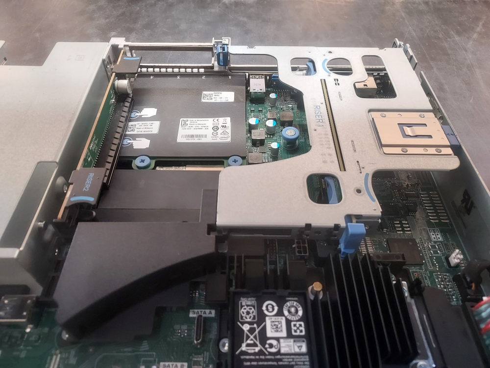
Both the R640 8 and 10 bay models use the same risers to provide PCIe connectivity to the system. The most common configuration is the 3 half height slot setup. This configuration has 2 risers. Riser 1 provides two low profile x16 half height slots. Both these slots are linked to CPU1. Riser 2 is linked to the second processor and provides a single x16 slot to the system. Riser 2 will not function without the presence of CPU2.
As mentioned there is also a chassis that has 2 full height slots. These are also x16 slots although this configuration is less common than the 3 slot low profile chassis. It is a good idea to have all available risers installed. Even if you don’t need them now you may need them in the future.
Building the server
You can test the server by installing the minimum amount of components required to boot. To boot you will need at least one of the following:
- CPU
- Memory
- Power supply
Required tools
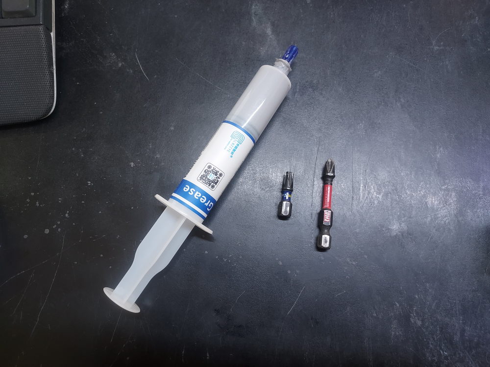
Not many tools are needed for this job. You will at the bare minimum need a Phillips head #2. A torque bit #30, some thermal paste, and electric air blower or can of compressed air.
Once again please note that in single CPU server configurations some components may be disabled – for example some slots or even entire risers could be rendered unusable.
Installing the processors
You will notice the slots for the CPU near the center of the chassis. They might be covered by the heatsinks or they could have a dummy CPU cover installed. The sockets will be labeled CPU1 and CPU2. Remove the heatsink or the cover prior to installing the CPU. Removal of the heatsink will reveal the CPU pins. You will have to depress the blue clips to remove the heatsinks and/or the CPU dummy cover. Don’t be alarmed if the clips break – this is common and unavoidable. You can replace them but its not entirely necessary.
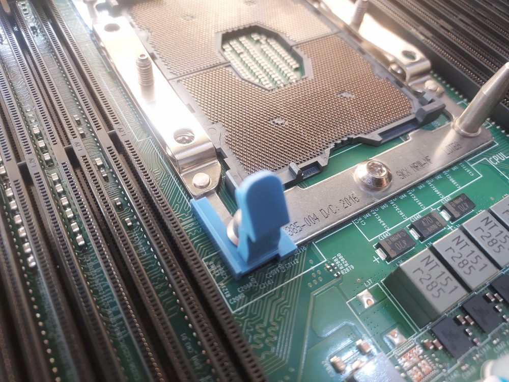
Now is the time to do a proper visual inspection of the CPU pins. Start by grabbing a can of compressed air and blow out any debris and dust. Look closely at the pins. They should not be bent or smashed in. Bent pins can cause a host of issues with memory and other aspects of the server like PCIe devices.
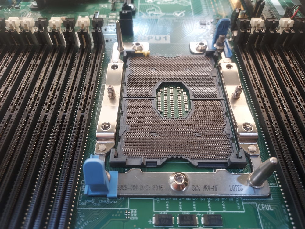
If you’ve determined the pins are in good condition you can now place the CPUs into the socket. Some people like to first snap the CPU into the heatsink prior to installing. I like to place the CPU into the socket by hand and then snap the heatsink on top of it. Do whatever is most comfortable for you. The reason I don’t always install the CPU into the heatsink is the fragility of the retention clips. At this point these servers are getting quite old and the plastic doesn’t always secure the CPU. I’ve had processors fall out of the heatsink as I flipped them down to install into the socket, and I’ve damaged pins as a result.
The most important part of this step is aligning the gold arrow on the CPU with the orientation arrow on the motherboard. Installing the CPU backwards can damage both the pins and the CPU if enough force is applied.
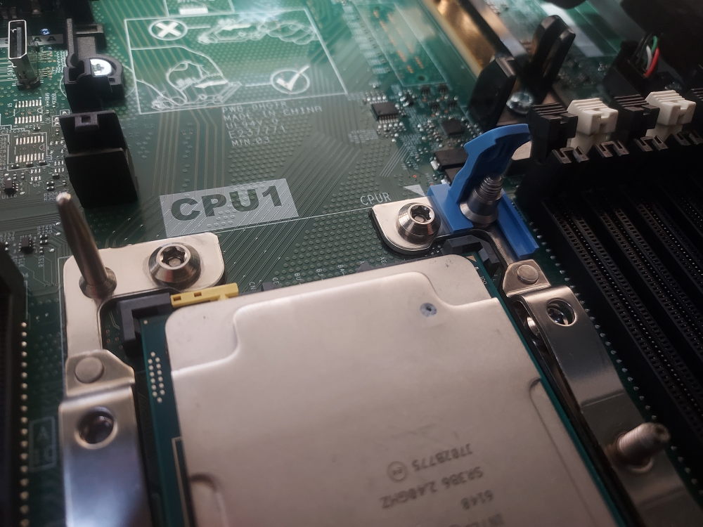
Apply thermal paste in an amount that will spread evenly across the entire face of the processor. Screw down the heatsink with a T30 bit.
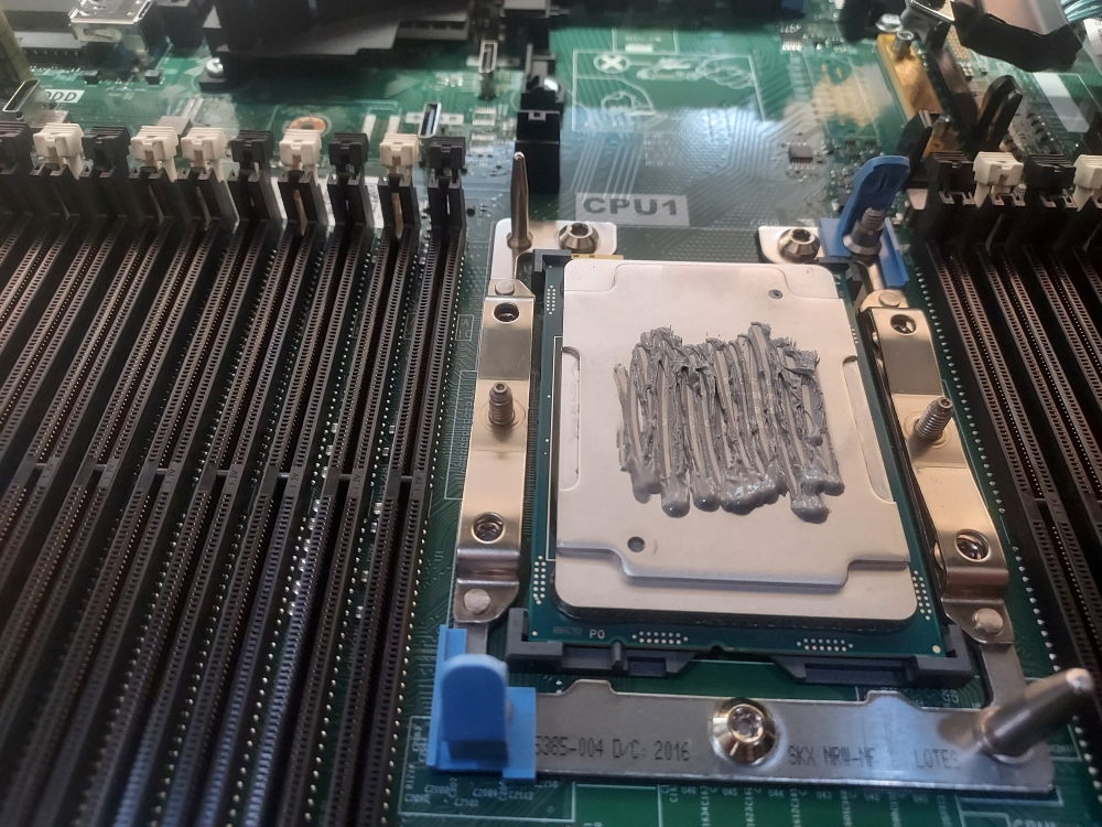
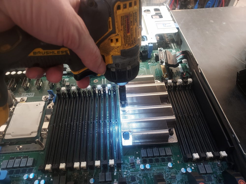
If you have a second CPU go ahead and populate the socket using the same method.
Installing the memory
Next, the memory can be installed. For the R640 platform there are 6 channels per CPU with each channel supporting 2 DIMMs each. This means for each processor there are a total of 12 DIMMs. I will include a channel mapping table below but you don’t really need it – simply populate the white DIMMs first and if you run out of those start populating the black DIMMs. Each white DIMM is a different channel and it’s recommended to spread memory across as many channels as you can. However you populate the DIMMs on one processor you should mirror the configuration on the other.
Let’s say you have a total of 8 sticks you want to spread across both processors. The recommended configuration would be to populate DIMMs A1,A2,A3,A4 and then DIMMs B1,B2,B3,B4 on the second processor.
Click here to see R640 memory channel mapping table
| CPU (Socket) | Memory Channel | Primary DIMM (1 DPC) | Secondary DIMM (2 DPC) |
|---|---|---|---|
| Socket 01 (CPU1) | Channel 0 | A1 | A7 |
| Channel 1 | A2 | A8 | |
| Channel 2 | A3 | A9 | |
| Channel 3 | A4 | A10 | |
| Channel 4 | A5 | A11 | |
| Channel 5 | A6 | A12 | |
| Socket 02 (CPU2) | Channel 0 | B1 | B7 |
| Channel 1 | B2 | B8 | |
| Channel 2 | B3 | B9 | |
| Channel 3 | B4 | B10 | |
| Channel 4 | B5 | B11 | |
| Channel 5 | B6 | B12 |
Now install the DIMM into the primary DIMM of the first channel (A1)
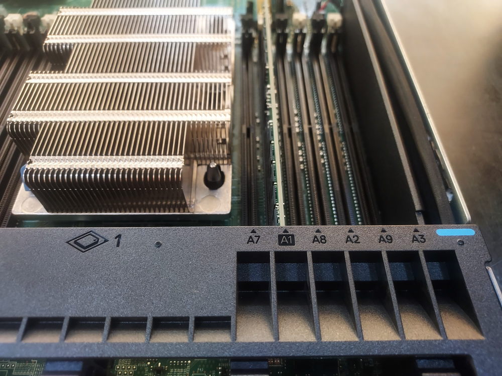
Now mirror the configuration for the second CPU (B1):
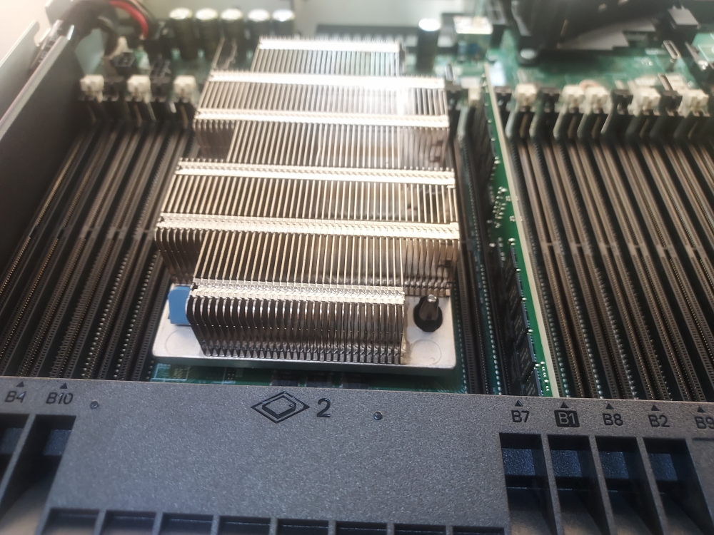
If you have more memory continue to populate the DIMMs in the order suggested above.
Installing a RAID controller
In order for drives to be exposed on the system you will need to wire the backplane to a RAID or HBA controller. You can wire the backplane directly to the motherboards onboard controller but this will only expose Sata drives. If you want to use both SAS and Sata drives you will need to install a controller. In this guide we will install an H730P mini mono controller.
First make sure you have the cable mentioned at the beginning of this guide. There are 2 mini SAS HD ports on the backplane. The cable will plug into these ports and be routed along the right side of the chassis where it terminates at the mini mono slot below:
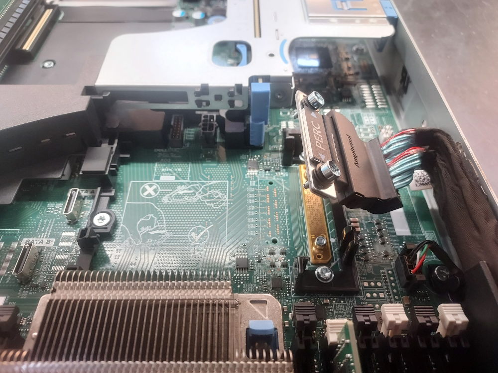
Place the controller in the slot by sliding edge of the controller under the black plastic retention clips:
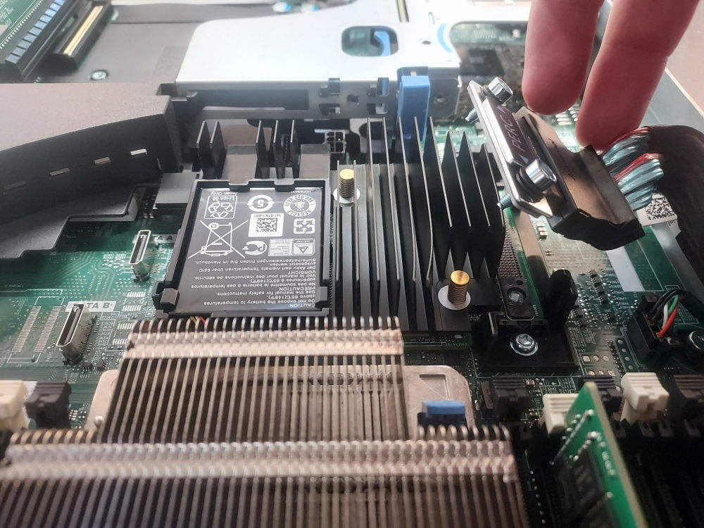
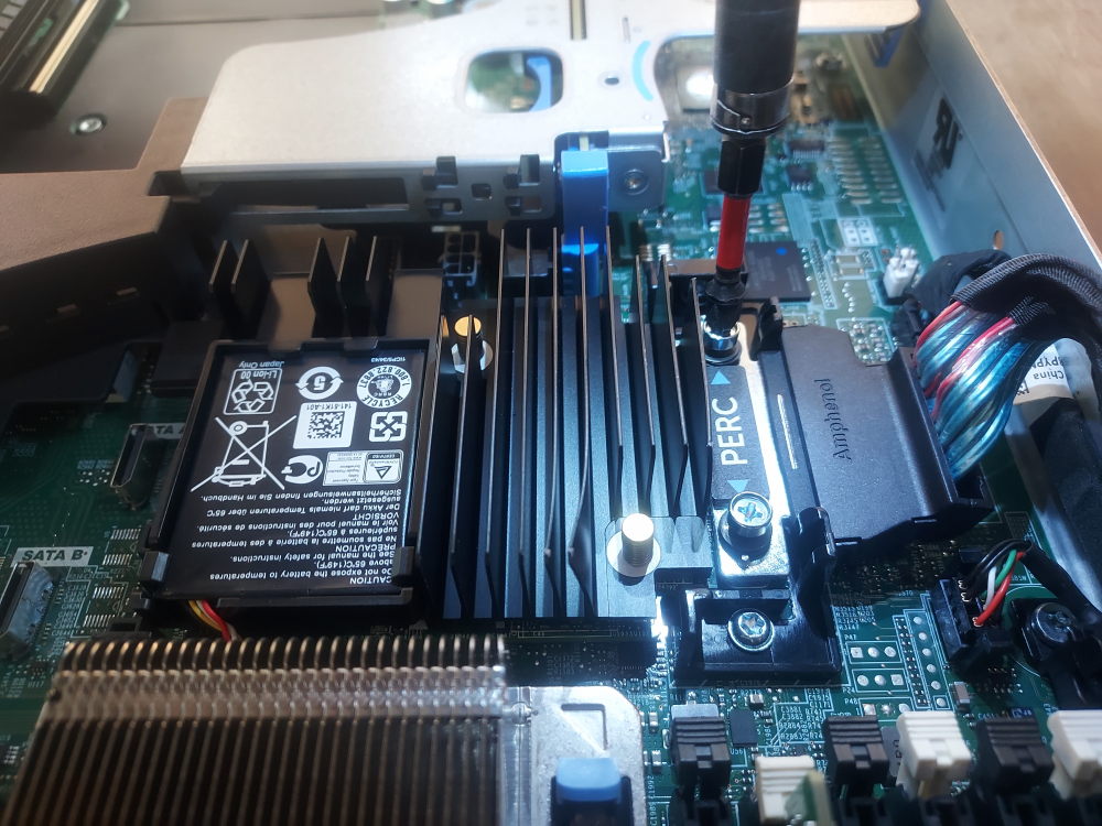
finally, screw down PERC cable with a phillips head #2:
Installing the NDC
Now it’s time to install the NDC (network daughter card.) To achieve this you must first remove riser 2 as well as the black plastic cover shown in the photo below:
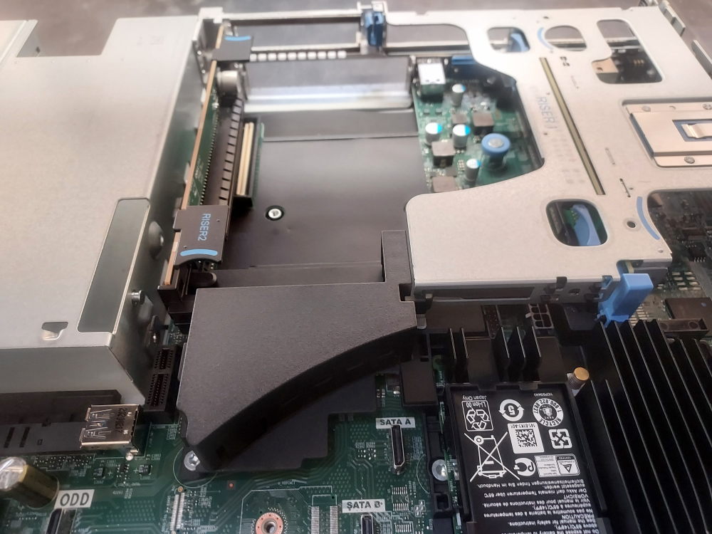
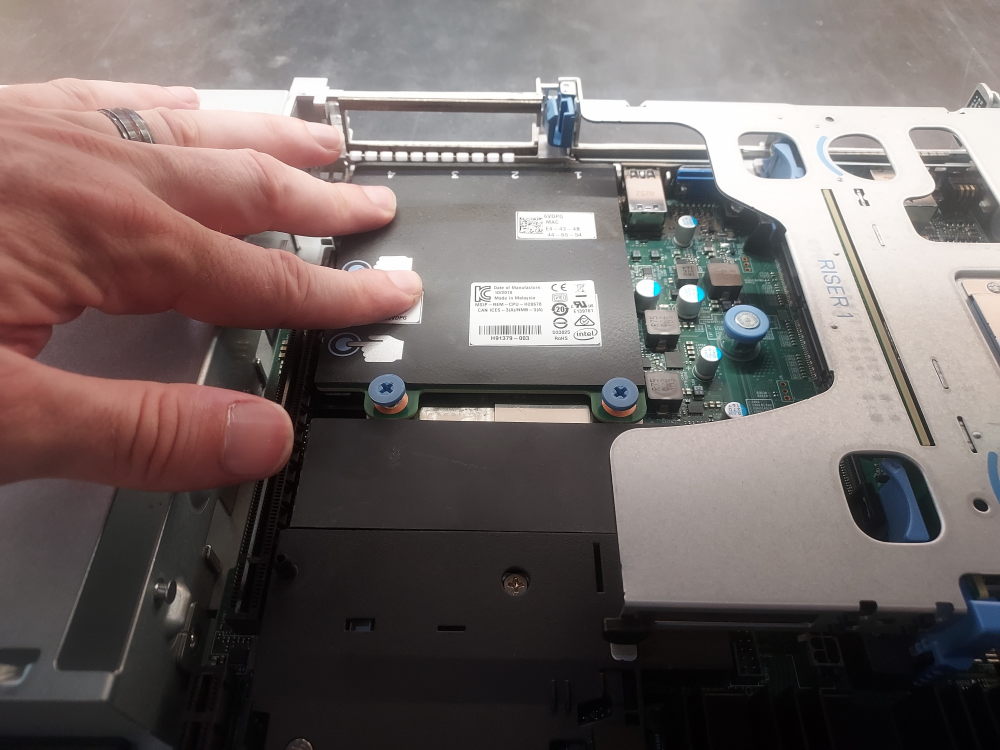
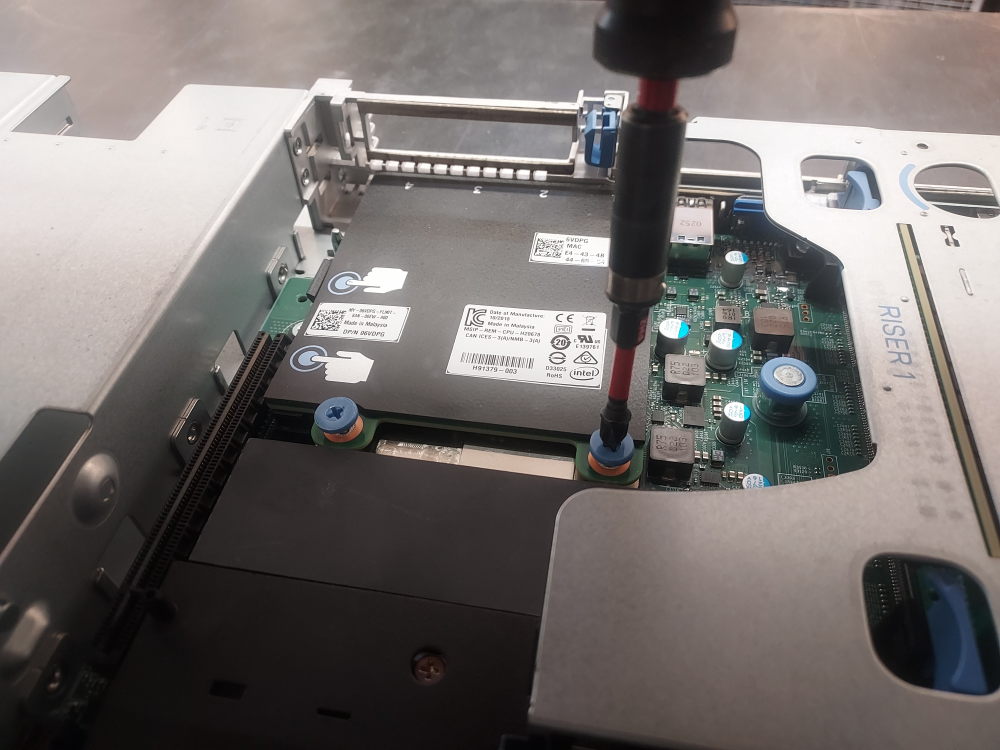
At this point reinstall both riser 2 and the black plastic cover.
Installing the power supplies
The last component to install are the power supplies. They slide in from the rear of the chassis.
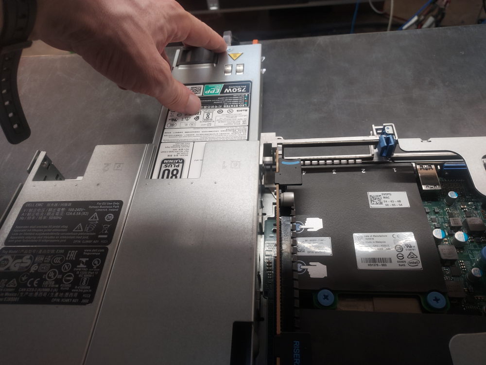
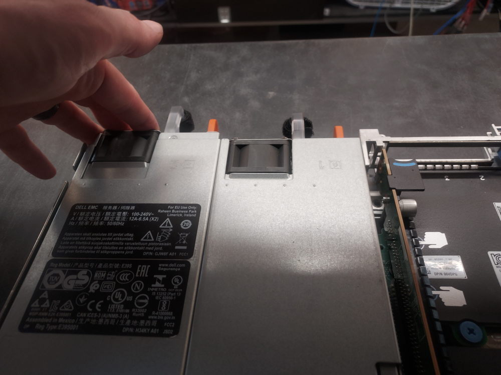
The server is now ready to be powered up.
Compatible parts
For a complete list of compatible parts for this server please read the following post.
Leave a Reply