I came across a 4 Bay LFF Supermicro server at work (X11SSH-F) and needed to give it an update.
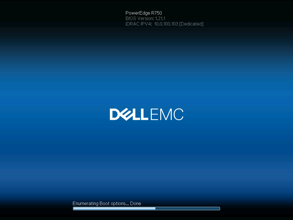
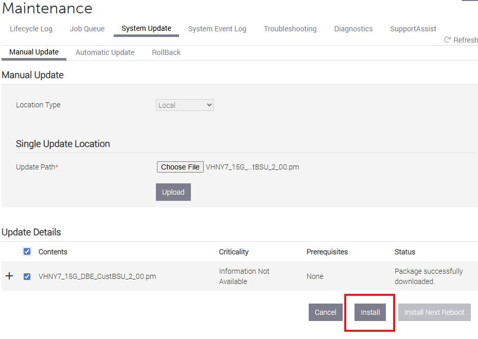
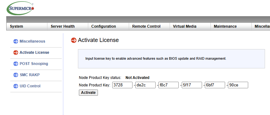
This particular server allowed me to update the BMC but required a license to install the BIOS as seen in the following screenshot:
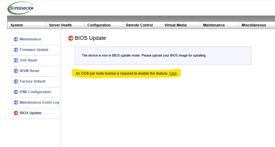
This is always frustrating when you’re just trying to complete the most bonehead level maintenance. Googling the error led me to the following reddit post which led me to the following perl script on Github.
I thought I would expand upon these resources with a step by step guide of downloading the script, running the script, and taking care of a few dependencies to make the script work.
I accomplished all of the following by booting a live version of Ubuntu. If you already have Ubuntu or some other distribution installed on your server that is just as good.
So the first order of business is booting into Ubuntu before following the next steps.
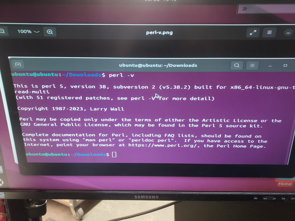
Step 1: Check if Perl Is Installed
Most Ubuntu installations already include Perl. To verify, open a terminal and run:
perl -vIf Perl is installed, you’ll see version information displayed in the terminal:
If you get a “command not found” message, install Perl with:
sudo apt update
sudo apt install perl
Step 2: Install the Required Perl Module
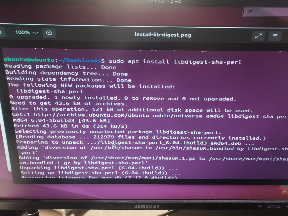
The script uses the Digest::SHA module to calculate an HMAC-SHA1 hash. Ubuntu provides this module as a package.
Install it by running:
sudo apt install libdigest-sha-perlAlternatively, if you prefer using CPAN, you can install it with:
cpan Digest::SHA
Step 3: Save the Script
Copy the Perl code from this github page into a new file. For example:
supermicro-ipmi-key.plSave the file somewhere convenient, such as your home directory.
Step 4: Make the Script Executable (Optional)
You can run the script directly by making it executable:
chmod +x supermicro-ipmi-key.plWhile this step isn’t strictly necessary, it makes running the script a little cleaner.
Step 5: Run the Script
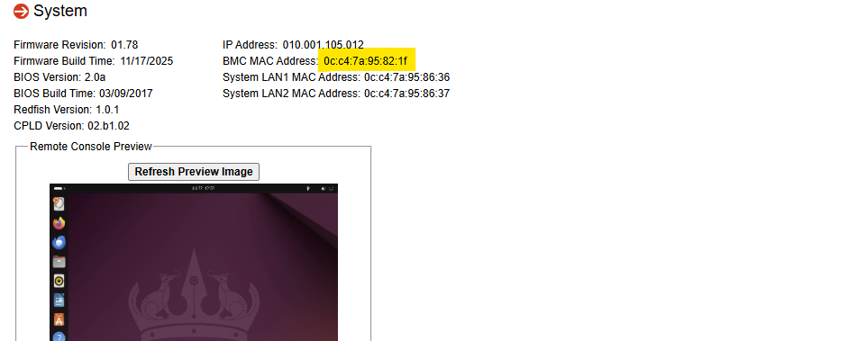
To run the script you simply invoke it and pass the MAC address of your BMC as an argument.You can find the MAC here in the IPMI web admin page:
You have two options.
Run it directly:
./supermicro-ipmi-key.pl 00:25:90:12:34:56Or execute it with Perl:
perl supermicro-ipmi-key.pl 00:25:90:12:34:56Replace the sample MAC address with the MAC address of your server’s BMC (IPMI) interface.
If everything is configured correctly, you’ll receive a generated key similar to:
3A1F 7B82 C4D0 E1F9 A5B3 8C2D
Punch this into the license field located here:
Troubleshooting Common Errors
“Can’t locate Digest/SHA.pm in @INC”
This means the required module isn’t installed.
Simply run:
sudo apt install libdigest-sha-perland try again.
“Usage: supermicro-ipmi-key <MAC>”
This message appears when no MAC address is provided.
Be sure to include the BMC MAC address when running the script.
“Invalid mac address”
The script expects the MAC address in the standard format:
AA:BB:CC:DD:EE:FFDouble-check that your address uses six hexadecimal pairs separated by colons.