This post will describe the process of updating DELL servers. The documentation will be split into 2 parts. Part 1 will describe the update process for 13 gen servers, or more specifically, any server that ships with the iDRAC 8 management system. Newer generations of servers starting with 14 gen ship with iDRAC 9 which is a slightly different process.
Updating 13 gen servers (iDRAC 8)
DELL use to have an easy online updater but since 2025 this service has been down. Now you must update using the local method. Local means the updates are first downloaded to your machine directly from DELL, and then uploaded to the server.
To upload an update you must first obtain the IP address of the server. For communication to take place both your local machine and the server need to be on the same network. Often times you will receive a server that has a static address set by the previous owner. This must be changed so the server gets all of its networking information from the local DHCP server.
First enter into the BIOS by hitting the F2 key during boot time:
Then arrow down to iDRAC settings and hit enter:
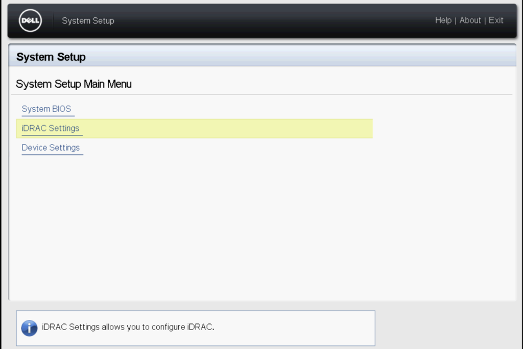
Resetting iDRAC
It is not mandatory but highly recommended that you reset iDRAC prior to updating the server or updating the network configuration. Resetting iDRAC can resolve many hidden issues you may not see until it’s time to update. Resetting also clears out any custom passwords set by the previous owner of the server.
Once in the iDRAC settings scroll all the way down:
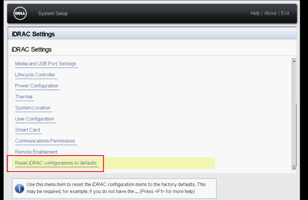
Highlight Reset iDRAC configurations to defaults and hit enter and then confirm. Wait until the system tells you that the process completed successfully.
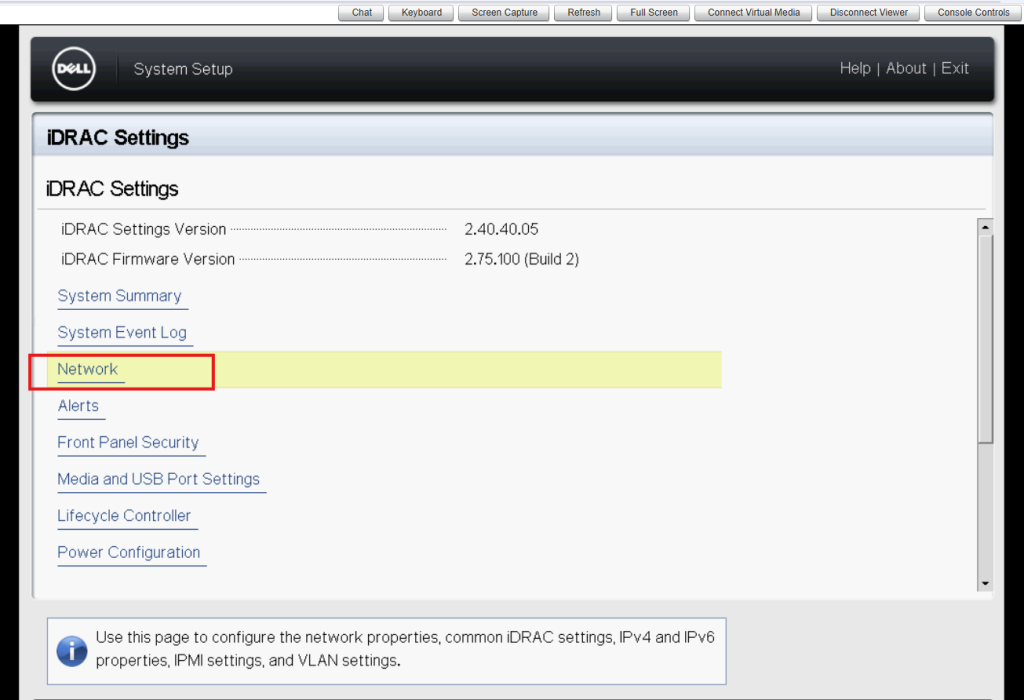
Configuring the network
Now it’s time to properly configure the network. Return to the main screen in iDRAC Settings and arrow down to Network:
From here scroll down to the section labeled IPV4 Settings. Make sure your settings match the following screenshot:
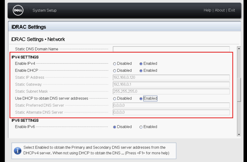
Once properly configured hit ESC until you are asked to save the changes. Save the changes and continue hitting escape until the server resumes the boot process. Hit CTRL-ALT-DELETE. You must reboot the server to refresh the IP address displayed at boot time.
Here you can see the new IP address is displayed during boot time:
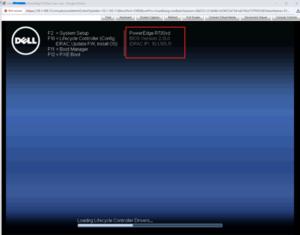
Make note of the IP address as the server boots and plug this IP into your web browser.
If a proper network connection has been established you will be greeted with a login prompt. If you’ve never logged into the server before your computer will warn you of an unsecure connection. Go ahead and continue through the warning to reach the login page.
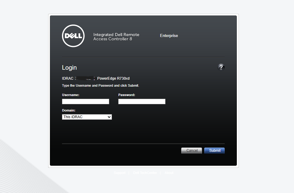
Login to the server with the following credentials:
Username: root
Password: calvin
If the default credentials do not work you need to reset iDRAC as described previously.
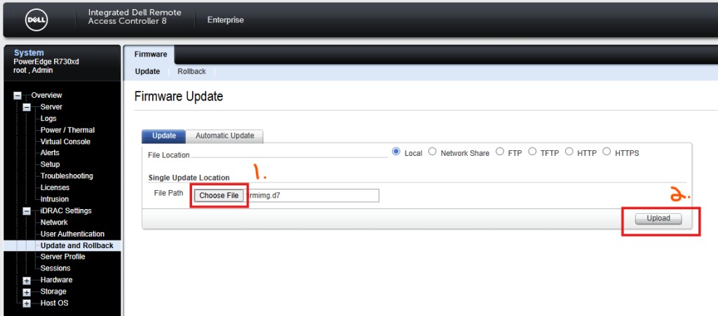
Expand iDRAC Settings and select Update and Rollback:

Here is where you will upload the individual updates. There’s a few things to keep in mind. Firstly, each server will have its own BIOS file. Some servers will share the same BIOS. Other servers require its own unique BIOS file.
Refer to the following table to see which servers share the same BIOS and which ones differ:
BIOS-sharing groups in 13G
| BIOS Family |
Servers |
| R630 Platform BIOS |
PowerEdge R630, PowerEdge R730, PowerEdge R730xd |
| R430 Platform BIOS |
PowerEdge R430, PowerEdge R530 |
| R330 Platform BIOS |
PowerEdge R330, PowerEdge T330 |
| R230 Platform BIOS |
PowerEdge R230, PowerEdge T130 |
| R930 Platform BIOS |
PowerEdge R930 only |
| R830 Platform BIOS |
PowerEdge R830 only |
| FC630 Platform BIOS |
PowerEdge FC630 only |
| M630 Platform BIOS |
PowerEdge M630 only |
| T630 Platform BIOS |
PowerEdge T630 only |
The 2 most important updates you must apply are the BIOS and iDRAC updates. These can be located on the DELL website under drivers.
Once you have the update simply click on choose file. Browse to the update file and then click upload. Here we will update the iDRAC firmware. iDRAC firmware is the same across all platforms that use the iDRAC 8 interface.
After your file is uploaded the server will give you the option to install. Put a checkmark next to the update and then click install.
Depending on the type of update the server may reboot. BIOS updates always require a reboot. This is done automatically. Other updates like iDRAC do not require a reboot.
You can monitor the update in the Job Queue. You will be asked if you want to go to the queue once you click install.
A successful update looks like the following:
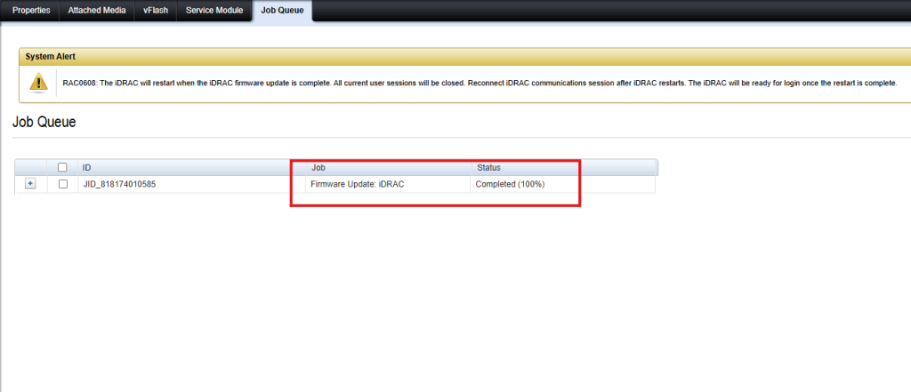
After updating the iDRAC you will be logged out. Simply log back into the server and repeat the previous steps for the other updates.
Updating iDRAC 9 Servers
DELL 14/15/16 use iDRAC version 9 so the following documentation can be used to update these generations of servers.
Follow the previous steps to reset iDRAC back to default settings and configure the network. These steps have not changed.
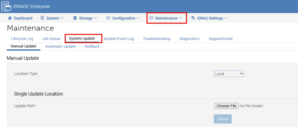
Once logged in to the iDRAC 9 interface click Maintenance and then System Update:
In the dropdown menu labeled Location Type, select HTTPS. For HTTPS Address type in downloads.dell.com.
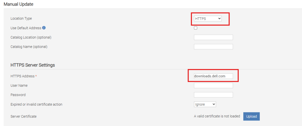
At the bottom click Check For Updates.
The server will then reach out to DELL to see what updates are available for your system.
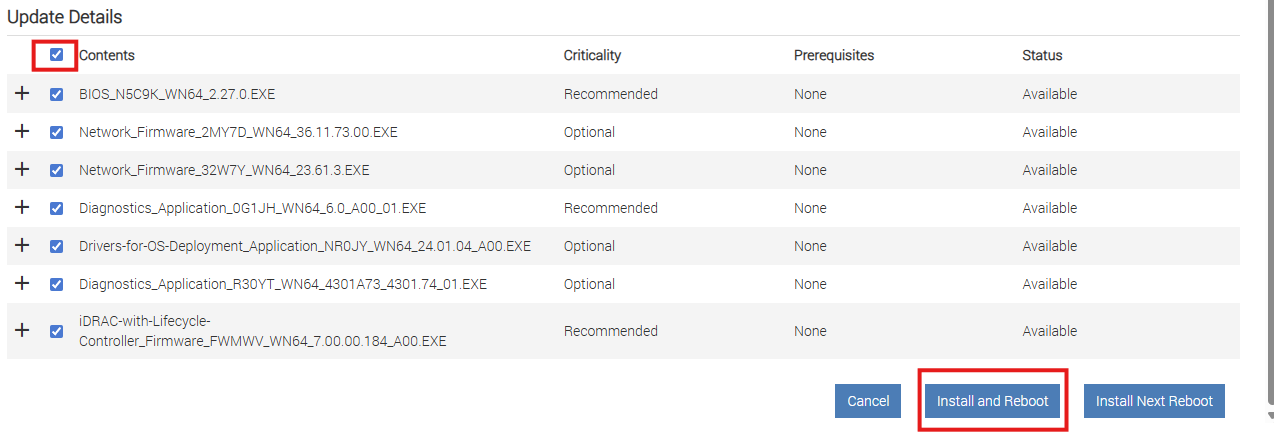
Put a checkmark next to all the updates it finds and then click install and reboot.

The server may reboot multiple times. Allow the server to finish the process and do not unplug power until the update process has completed.
You can view the progress of the updates by monitoring the Job Queue.
Troubleshooting
It is possible that you don’t have the option to download updates because you have a very old version of iDRAC or have an EXPRESS license. In some cases an Enterprise license is required to download updates from the internet.
You might also find that iDRAC did not update during the process but everything else did. In such a case it’s necessary to stair step the iDRAC update.
As an example, you cannot jump from version 3.20 all the way to the latest version. You must first update to 3.30 before attempting to update to the latest version.